
SONAR User Manual
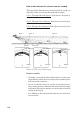
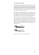
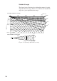
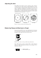


Table Of Contents
- SAFETY INSTRUCTIONS
- TABLE OF CONTENTS
- FOREWORD
- CONTROL DESCRIPTION
- OPERATIONAL OVERVIEW
- FINE TUNING THE PICTURE
- MARKS AND DATA
- MENU OVERVIEW
- FUNCTION KEYS
- ADVANCED LEVEL OPERATION
- Finding Fish School Center
- Tracking a Fish School (target lock)
- Detecting Fish Schools Aurally
- The Fish Alarm
- Relocating Fish School for Easy Observation
- Comparing of Fish School Concentration
- Measuring Fish School Speed
- The Event Mark
- True Motion Display
- Plotting Net Location Mark
- Observing Net Behavior
- Target Slice Display
- PORT/STARBOARD, HORIZONTAL SLICE DISPLAYS
- MEMORY CARD OPERATIONS
- TURNING MARKS, DATA ON/OFF
- INTERPRETING THE DISPLAY
- WARNINGS
- SELF TESTS
- INPUT DATA SELECTION
- MAINTENANCE
- MENU TREE
- SPECIFICATIONS
- INDEX
2-5
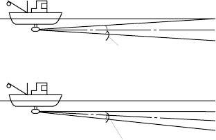
Tilt angle for surface fish
Sound emitted from the sonar transducer forms a circle-shaped
beam with a width of approximately 12 degrees in the vertical
direction (vertical beam width). The tilt angle is indicated by the
angle between the center line of the beam and the horizontal
plane. Then, if the tilt angle is set to 0 degrees, the center line is
parallel with the sea surface and one half of the emitted sound
goes upward, toward the sea surface.
This causes one half of the emitted sound to be reflected toward
the transducer and displayed on the screen as sea surface reflec-
tions. When the sea is calm, since the sound is reflected just like
a light hitting a mirror at a narrow incident angle, it propagates
away and the sea surface reflections become negligible.
However if the sea is not calm enough, they will become domi-
nant and interfere with observation of wanted echoes. To mini-
mize these sea surface reflections and to search surface fish
schools effectively, the tilt angle is usually set between 5 and 6
degrees so the upper portion of the beam becomes almost paral-
lel with the sea surface. When the sea is rough, it is often set to a
little larger angle.
Tilt angle 0°
Surface
Tilt angle 5-6°
Surface
12°
12°
Figure 2-2 Tilt angle and sea surface reflections