OPERATOR'S MANUAL NETWORK FISH FINDER Model DFF1-UHD www.furuno.
IMPORTANT NOTICES General • This manual has been authored with simplified grammar, to meet the needs of international users. • The operator of this equipment must read and follow the descriptions in this manual. Wrong operation or maintenance can cancel the warranty or cause injury. • Do not copy any part of this manual without written permission from FURUNO. • If this manual is lost or worn, contact your dealer about replacement.
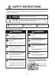
SAFETY INSTRUCTIONS The user and installer must read the appropriate safety instructions before attempting to install or operate the equipment. WARNING Indicates a potentially hazardous situation which, if not avoided, could result in death or serious injury. CAUTION Indicates a potentially hazardous situation which, if not avoided, may result in minor or moderate injury.
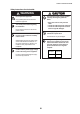
SAFETY INSTRUCTIONS Safety instructions for the installer WARNING CAUTION The transducer cable must be handled carefully, following the guidelines below. Do not open the equipment. Only qualified personnel should work inside the equipment. • Keep fuels and oils away from the cable. • Locate the cable away from chemicals. • Locate the cable away from locations where it might be damaged. Turn off the power before beginning the installation. Fire or electrical shock can result if the power is left on.
TABLE OF CONTENTS FOREWORD ....................................................................................................................v SYSTEM CONFIGURATION ..........................................................................................vi 1. INSTALLATION ........................................................................................................1 1.1 Equipment Lists.............................................................................................................
FOREWORD A Word to the Owner of the DFF1-UHD Congratulations on your choice of the FURUNO DFF1-UHD Network Fish Finder. We are confident you will see why the FURUNO name has become synonymous with quality and reliability. Since 1948, FURUNO Electric Company has enjoyed an enviable reputation for quality marine electronics equipment. This dedication to excellence is furthered by our extensive global network of agents and dealers.
SYSTEM CONFIGURATION NavNet Equipment TZT9/14/BB Ethernet HUB HUB-101 NETWORK FISH FINDER DFF1-UHD 12-24 VDC Rectifier PR-62 External KP 100/110/ 220/230 VAC 1ø, 50/60 Hz Speed/Temperature Sensor ST-02MSB ST-02PSB Transducer B265LH or CM265 LH vi Temperature Sensor T-02MTB T-02MSB T-03MSB
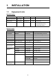
1. INSTALLATION 1.1 Equipment Lists Standard supply Name Type Code No. Qty Remarks Network Fish Finder DFF1-UHD — 1 Spare Parts SP02-05601 001-033-740 1 set Fuse (2 pcs.) Installation Materials CP02-08500 000-011-917 1 set - Power cable assy. (3.5 m) - LAN cable assy. (5 m) - Self-tapping screws Optional supply Name Type Code No.
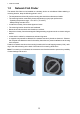
1. INSTALLATION 1.2 Network Fish Finder The network fish finder can be installed on a desktop, deck or on a bulkhead. When selecting a mounting location, keep the following points in mind: • The temperature and humidity at the mounting site should be moderate and stable. • The mounting location must satisfy these requirements to get proper performance. - Operating temperature range: -15 to 55°C (-27 to 99°F) - Waterproofing standard: IP22 • Locate the unit away from exhaust pipes and vents.
1. INSTALLATION 1.3 Transducer The performance of the fish finder largely depends upon the transducer position. Select a place least affected by air bubbles since turbulence blocks the sounding path. The face of the transducer must be facing the sea bottom in normal cruising trim of the boat. Further, select a place least influenced by engine noise. It is known that air bubbles are fewest at the place where the bow first falls and the next wave rises, at usual cruising speed.
1. INSTALLATION 1.5 Optional Temperature Sensors 1.5.1 Transom mount temperature sensor T-02MTB • Fix the cable at a convenient location with cable clamp. • When the cable is led in through the transom board, make a hole of approx. 17 mm in diameter to pass the connector. After passing the cable, fill the hole with a sealing compound. D>50cm D 5x20 Mount sensor flush with hull bottom.
1. INSTALLATION 1.5.2 Thru-hull temperature sensor T-02MSB, T-03MSB Select a suitable mounting location considering the following points. • Select a mid-boat flat position. The sensor does not have to be installed perfectly perpendicular. However, the location should not be such that the transducer may be damaged when the boat is dry-docked. • Locate away from equipment which gives off heat. • Locate away from drain pipes. • Select a location where vibration is minimal.
2. WIRING 2.1 Wiring Outline Connect the power cable, transducer cables, sensor cable, network cable and ground wire to their respective locations on the network sounder. See the next page for how to connect the transducer cables. TZT9/TZT14/ TZTBB To HUB-101 MOD-Z072-050+, 5 m (option: 2/10 m) DFF1-UHD EXT-KP 12-24 VDC 2.8-1.4 A TRANSDUCER TEMP MJ-A3SPF0013-035C (3.
2. WIRING 2.2 Transducer Cable, Cable for External KP (option) If the external KP is not to be connected, do only the applicable procedures in sections 2.2.1 and 2.2.2. The KP from an echo sounder or sonar can be connected to this network fish finder to synchronize transmission (to prevent interference). Use the optional Connector Kit for TX Sync (Type, OP0286, Code No. 001-205-780) and cable MPYC-4 (or MPYC-2) for the connection. (The MPYC-4 is a Japan Industrial Standard (JIS) cable.
2. WIRING How to process the cable for the external KP 1. Process the PH connector (02-1097, optional supply) as shown below. a) Make the length of the wires of the PH connector 100 mm. b) Remove the sheath from the cores 10 mm. c) Fold back the cores in half. d) Attach crimp-on lug NCW-1.25 to each core. (b) (a) Approx. 10 mm Approx. 100 mm (c) (d) Fold back core. 2. Remove the armor 170 mm and cut off the vinyl sheath 90 mm. MPYC-4 Armor Approx. 210 mm Approx. 90 mm Vinyl sheath 3.
2. WIRING 2.2.2 How to connect the transducer cable This procedure shows you how to connect the transducer cable. To connect both the transducer cable and the cable for external KP, go to section 2.2.3. 1. Open the cover: Grasp the cover at two sides, spread the cover slightly and lift. 2. Loosen five screws to remove the shield cover. 3. Detach the two WAGO connectors (TB3, TB4) inside the equipment. TB4 TB3 WAGO connector Clamp fixing plate WAGO connector opener 4.
2. WIRING 5. Loosen the two screws fixing the clamp fixing plate to detach the plate. Clamp fixing plate 6. Pass the sealing nut (unfastened at step 4) onto the transducer cable and pass the cable through the super gland and into the unit. 7. Use the WAGO connector opener, attached inside the equipment, to connect the transducer cable to the WAGO connectors, following the instructions in the figure below and the interconnection diagram. Push WAGO connector opener Twist. Core 1. Twist conductors. 2.
2. WIRING 10. Tighten the sealing nut according to the information in the table below. Transducer CM265LH B265LH Clearance Torque 1.8 - 2.0N/m 4 mm 2 mm Clearance 11. Reattach the shield cover and close the outer cover. 2.2.3 How to connect the transducer cable, cable for external KP 1. Remove the cover, shield cover and WAGO connectors, referring to steps 1-3 in section 2.2.2. 2. Unfasten the lock nut of the inside the unit to detach the super gland.
2. WIRING 6. Unfasten the nut material inside the unit. Nut material Clamp fixing plate Clamp Rainproofing panel 7. Using the two screws removed at step 5, fasten the upper two holes of the supplied rainproofing panel.
2. WIRING 8. TIghten the lock nut inside the unit to fasten the super glands (two pcs., see step 12). The torque for the lock nut shall be 1.8 - 2.0 N/m. Super gland (two pcs.) 9. Set the nut material (removed at step 6) inside the unit, align its two protrusions with the lower holes on the rainproofing panel. Use the remaining two screws removed at step 5 to fasten the lower two holes on the rainproofing panel. Fasten lower two holes 10. Use two screws to fasten the clamp removed at step 4.
2. WIRING 11. For the transducer cable and the cable for the external KP, pass each cable through its super gland, the supplied rainproofing panel and each hole in the unit. Then slip a lock nut onto each cable. (For the super gland of the cable for the external KP, unfasten the lock nut from the super gland then pass the cable through the super gland. See page 8 for how to treat the cable end.) Lock nut Cable for Ext.
2. WIRING 12. Transducer cable: Lay the transducer cable in the cable clamp then refasten the clamp fixing plate. Cable for the external KP: Lay the cable in the cable clamp and fix it with the supplied clamp fixing plate and two upset screws. Lock nut for super gland (2 pcs.) Clamp fixing plate Large: transducer cable Small: cable for external KP 13. Connect the cables as follows: • Transducer cable: See section 2.2.2. • Cable for external KP: See the illustration below.
2. WIRING 14. Attach the supplied EMI core (GRFC-10) to the cable for the external KP approx. 100 mm from the super gland. 10 mm Super gland (for ext. KP) EMI core 15. Attach the shield cover and close the outer cover.
2. WIRING 2.3 LAN Cable Do as follows to connect the supplied LAN cable (MOD-Z072-050+) or the optional LAN cable (MOD-Z072-020+, MOD-Z072-100+). 1. Unfasten the sealing nut from the LAN connector then remove the sealing insert and clamping claw. 2. Detach the sealing insert from the clamping claw as shown below. Seal assy. Super gland Sealing insert Insert seal Clamping claw Sealing nut How to detach clamping claw Hold the clamping claw/seal assy.
2. WIRING 3. Pass the sealing nut, clamping claw and sealing insert onto the LAN cable in the order shown in the figure below. Connect the cable to the LAN connector. (Note the orientation of the sealing insert when passing it onto the cable. Push the cable into the slit in the sealing insert.) LAN cable Sealing insert (Push cable into slit.) Clamping claw Sealing nut 4. Set the sealing insert and clamping claw into the sealing nut then tighten the nut. 5. Tighten the sealing nut to fasten the LAN cable.
3. INITIAL SETTINGS WARNING Do not open the equipment unless totally familiar with electrical circuits. Only qualified personnel should work inside the equipment. 3.1 DIP Switch Setting The DIP switch S2 sets up the system according to the equipment connected. In the default setting all switches (1-8) are OFF. The DIP switch S3 should not be adjusted; leave all switches in the OFF position. S3 4-1 DIP Switches (factory settings) 1-8 ON OFF S2 OFF ON DIP switch S2 description Switch No.
3. INITIAL SETTINGS #2 OFF ON Host name ES092002 ES092003 IP address 172.031.092.002 172.031.092.003 After setting up the transducer at the DFF1-UHD, set the transducer type at the NavNet device. See respective Installation Manual for the procedure. Note: DIP Switch S2 is for factory use. Do not change the settings. 3.2 Operation Check For NavNet TZtouch, the DFF1-UHD is powered on/off from ship’s switchboard. For NavNet 3D, it is powered on/off from the display unit.
4. MAINTENANCE NOTICE WARNING Do not apply paint, anti-corrosive sealant or contact spray to coating or plastic parts of the equipment. ELECTRICAL SHOCK HAZARD Do not open the equipment. Only qualified personnel should work inside the equipment. 4.1 Those items contain organic solvents that can damage coating and plastic parts, especially plastic connectors. Maintenance Regular maintenance is essential for good performance.
4. MAINTENANCE 4.2 How to Replace the Fuse The 5A fuse (Type: FGBO-A 125V 5A PBF, Code No. 000-155-853-10) in the snap-in fuse holder on the power cable protects the equipment from equipment fault and reverse polarity of the power supply. If the equipment cannot be powered, the fuse may have blown. Find out the cause for the blown fuse before replacing it. If the fuse blows again after replacement, contact a FURUNO agent or dealer for instructions. WARNING Use the proper fuse.
APPENDIX 1 JIS CABLE GUIDE Cables listed in the manual are usually shown as Japanese Industrial Standard (JIS). Use the following guide to locate an equivalent cable locally. JIS cable names may have up to 6 alphabetical characters, followed by a dash and a numerical value (example: DPYC-2.5). For core types D and T, the numerical designation indicates the cross-sectional Area (mm2) of the core wire(s) in the cable.
FURUNO DFF1-UHD SPECIFICATIONS OF NETWORK FISH FINDER DFF1-UHD 1 1.1 GENERAL TX frequency 50/200 kHz, alternative transmission 1.2 Output power 1 kW nominal 1.3 Amplifier type Straight amplifier (H/L gain switching available) 1.4 Depth range and Pulse repetition rate (PRR) at 200 kHz, TX rate: 20 Range (m) 2 5 10 40 100 400 1200 2 2.1 PRR (times/min, max.
PACKING LIST 02GL-X-9851 -0 DFF1-UHD A-1 N A M E ユニット 1/1 O U T L I N E DESCRIPTION/CODE № Q'TY UNIT ネットワーク魚探 1 DFF1-UHD NETWORK FISH FINDER 000-022-520-00 予備品 SPARE PARTS SP02-05601 ヒューズ 2 FGB0-A 125V 5A PBF GLASS TUBE FUSE 000-155-853-10 工事材料 INSTALLATION MATERIALS CP02-08500 +トラスタッピンネジ 1シュ 4 5X20 SUS304 SELF-TAPPING SCREW 000-162-608-10 ケーブル(組品)LAN 1 MOD-Z072-050+ LAN CABLE ASSEMBLY 000-167-176-10 ケーブル組品MJ 1 MJ-A3SPF0013-035C(5A) CABLE ASSEMBLY 000-157-939-10 図書 DOCUM
D-1
C B A 5 整流器 (+) 1 6 RECTIFIER (-) 2 PR-62 *2 3 NOTE *1: SHIPYARD SUPPLY. *2: OPTION. *3: CM265LH ONLY. 注記 *1)造船所手配。 *2)オプション。 *3)CM265LHのみ。 *1 100-115/ DPYC-1.5 220/230VAC, 1φ,50/60Hz 5A 8m *1 MPYC-4 KP IN KP OUT 1 2 3 4 5 6 SHIELD TEMP TEMP_0V SPEED 12V_P GND *1 IV-2sq.
FURUNO Worldwide Warranty for Pleasure Boats (Except North America) This warranty is valid for products manufactured by Furuno Electric Co. (hereafter FURUNO) and installed on a pleasure boat. Any web based purchases that are imported into other countries by anyone other than a FURUNO certified dealer may not comply with local standards.
FURUNO Warranty for North America FURUNO U.S.A., Limited Warranty provides a twenty-four (24) months LABOR and twenty-four (24) months PARTS warranty on products from the date of installation or purchase by the original owner. Products or components that are represented as being waterproof are guaranteed to be waterproof only for, and within the limits, of the warranty period stated above.
(Elemental Chlorine Free) The paper used in this manual is elemental chlorine free. FURUNO Authorized Distributor/Dealer 9-52, Ashihara-cho, Nishinomiya, 662-8580, JAPAN All rights reserved. Printed in Japan Pub. No. OME-20400-B (DAMI) DFF1-UHD A: JAN. 2013 B: JAN.