
Operator's Manual


6
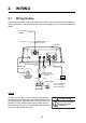
2. WIRING
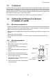
2.1 Wiring Outline
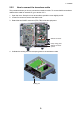
Connect the power cable, transducer cables, sensor cable, network cable and ground wire to their
respective locations on the network sounder. See the next page for how to connect the transducer
cables.
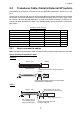
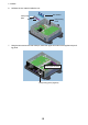
Ground
Connect a ground wire (IV-2 sq, local supply) between the
ground terminal and ship’s ground to prevent interference to
the sounder picture. Make the length of the wire as short as
possible. For FRP vessels, install a ground plate that mea-
sures about 20 cm by 30 cm on the outside of the hull bottom
and connect the ground wire there.
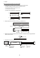
DFF1-UHD
BATTERY
White
Black
Shield (green)
12 - 24 VDC
MJ-A3SPF0013-035C
(3.5 m)
Temperature or
Speed/Temperature
Sensor*
GROUND
Ground wire
(IV-2 sq)
12-24 VDC
2.8-1.4 A
MOD-Z072-050+, 5 m
(option: 2/10 m)
TEMP
Transducer
External
KP
EXT-KP TRANSDUCER
* For no connection,
cover connector
with supplied cap.
To HUB-101
TZT9/TZT14/
TZTBB
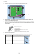
CAUTION
Ground the equipment
to prevent mutual
interference.