DOPPLER SPEED LOG Marine Speed and Distance Measuring Equipment (SDME) DS-80
Your Local Agent/Dealer 9-52 Ashihara-cho, Nishinomiya, Japan Telephone : 0798-65-2111 Telefax : 0798-65-4200 All rights reserved. Printed in Japan FIRST EDITION : FEB. 2000 M1 PUB.No. OME-72470 ( DAMI ) DS-80 : FEB.
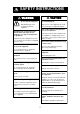
SAFETY INSTRUCTIONS CAUTION WARNING ELECTRICAL SHOCK HAZARD Do not open the equipment. Do not use the equipment for other than its intended purpose. Only qualified personnel should work inside the equipment. Improper use of the equipment can result in personal injury or equipment damage. Turn off the equipment immediately if you feel it is abnormal. Immediately turn off the power at the switchboard if water leaks into the equipment or an object is dropped into the equipment.
WARNING LABEL A warning label is attached to the Distributor, Transceiver and Terminal Box. Do not remove the labels. If a label is missing or is illegible, contact a FURUNO dealer or agent about replacement. WARNING To avoid electrical shock, do not remove cover. No user-serviceable parts inside. Name: Warning Label (1) Type: 86-003-1011-0 Code No.: 100-236-230 RECORD OF MODIFICATIONS IN THIS OPERATOR’S MANUAL Pub No. Software (Prog. No.
TABLE OF CONTENTS SPECIFICATIONS ....................... SP-1 2 OPERATION OF OPTIONAL EQUIPMENT .............................. 12 FOREWORD...................................... 1 SYSTEM CONFIGURATION ............. 2 PRINCIPLE OF OPERATION............ 3 REMARKS ON USAGE..................... 4 2.1 Digital Indicator DS-830, Distance Indicator DS-840............................12 3 MAINTENANCE, TROUBLESHOOTING................ 14 1 OPERATION OF DISPLAY UNIT . 5 3.1 Maintenance .............................
This page is intentionally left blank.
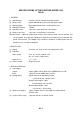
SPECIFICATIONS OF THE DOPPLER SPEED LOG DS-80 1. GENERAL (1) Speed Range Fore-Aft: -10.0 to +40 knots through-the-water (2) Distance Run 0.00 to 999,999.99 nautical miles through-the-water (3) Working Depth Water depth greater than 3 m beneath the keel. (4) Working Frequency 1.0 MHz (5) Speed Accuracy 1.0% or 0.1 knots whichever is the greater (6) Distance Accuracy 1.0% or 0.
4. POWER SUPPLY (1) System Source 100/110/115/200/220/230 VAC:1.5/0.7 A max., 1 phase, 50-60 Hz 5. ENVIRONMENTAL CONDITION (IEC 60945) (1) Ambient Temperature -15°C to +55°C (units for protected area) Analog display: 0°C to +50°C (2) Relative Humidity 95% at 40°C (3) Vibration IEC 60945 adopted (4) Category of Equipment Display Unit/Distance indicator/Transceiver Unit: For protected area Transducer: For submerged use, 600 kPa x 12 h Distributor/Terminal box: For protected area 6.
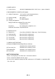
FOREWORD Foreword Features Thank you for purchasing the FURUNO DS-80 Doppler Speed Log. We are confident you will discover why FURUNO has become synonymous with quality and reliability. The FURUNO DS-80 displays ship’s speed relative to water, using the Doppler principle; ship’s speed is measured by detecting the Doppler shift frequency from the signal returned from the watermass.
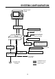
SYSTEM CONFIGURATION DISPLAY UNIT DS-800 TERMINAL BOX DS-802 DIMMER MF-22L-1/MF-22L-2 IEC 61162-1 Input Power ON SW Signal Distance Run Signal IEC 61162-1 Output DISTRIBUTION BOX DS-801 DIMMER MF22L-1/MF22-2 TERMINAL BOX DS-802 JUNCTION BOX CI-630 TRANSCEIVER UNIT DS-810 DIGITAL INDICATOR DS-830 DISTANCE INDICATOR DS-840 DIMMER MF-22L-1/MF-22-2 RANGE SWITCH BOX DS-389 115/230 VAC ANALOG DISPLAY UNIT MF-22A-1 SHIP'S MAINS 115/230 VAC : STANDARD SUPPLY TRANSDUCER DS-820 : OPTIONAL SUPPLY : LOCAL
PRINCIPLE OF OPERATION The Doppler speed log measures ship's speed by using the Doppler Effect, which is observed as a frequency shift resulting from relative motion between a transmitter and receiver or reflector of acoustic or electromagnetic energy. A common example of the Doppler Effect is a train. When a train is approaching, the whistle has a higher pitch than normal. You can hear the change in pitch as the train passes.
REMARKS ON USAGE Remarks on Usage The accuracy will not be affected by: • - water temperature (sound velocity) The DS-80 measures ship’s speed by detecting the Doppler shift frequency of the echo reflected by a watermass (water layer containing plankton and other microorganisms) located within the measuring area, which is usually about 2 m. In some instances, however, no signal is returned because of too few plankton in the sensing depths.
1 OPERATION OF DISPLAY UNIT 1.1 Controls Omnipad Selects items, options on menus. Opens/closes the menu. MENU ENT Registers options on menus. Selects display; speed plus distance or speed. DISP DIM Adjusts panel illumination. Adjusts LCD contrast. * DS-80 1.2 PWR Turns power on/off. Turning the Power On/Off 1.2.1 Power on 1.2.2 Power off Press the [POWER] switch to turn on the equipment. The last-used display appears. The example below shows the speed and distance run.
1.3 Adjusting Contrast, Panel Dimmer 1.4 Selecting a Display Press the [DISP] key to select display desired. Each time the key is pressed the display shows speed and distance run or speed alone as below. 1.3.1 Contrast 1. Press the [*] key to open the contrast adjustment dialog box. Direction : Fore : Aft CONTRAST (0~63) 41 SPEED EXIT: [ENT] STW 10.0 12.50 kt 2. Press the Omnipad at or to adjust the contrast. The setting range is 0 to 63 and the default setting is 48. DISTANCE nm 3.
1.5 5. Press the [MENU] key twice to close the menu. (Some menus require only a single pressing of the [MENU] key.) Main Menu Operation Functions of the DS-80 are selected through the menu. To enter numerical data 1. Press the [MENU] key to open the menu. Some menus require input of numeric data. This is done with the Omnipad. MENU DISTANCE RUN DISPLAY DEMO SYSTEM MENU SYSTEM MENU2 1. Select the digit or sign (+ or -) to change with or on the Omnipad. (The cursor shows the digit or sign selected.
The cursor circumscribes the leftmost digit of the distance run figure. MENU DISTANCE RUN DISPLAY DEMO SYSTEM MENU SYSTEM MENU2 DISTANCE RUN DISPLAY 2. Press the Omnipad at to select DISTANCE RUN DISPLAY and press the [ENT] key. Cursor DATA DISPLAY CONTACT CLOSURE RESET OFF SET 000000.00nm ENT SET 4. Press the Omnipad at the digit to change. DISTANCE RUN DISPLAY DATA DISPLAY CONTACT CLOSURE RESET OFF SET 0.00nm ENT SET or to select 5. Press the Omnipad at or to change value.
5. Press the [ENT] key to finish and press the [MENU] key twice to close the menu. 3. Select averaging time period desired among 15, 30, 45 and 60 seconds. The distance run indication reads 0.00. 5. Press the [MENU] key twice to close the menu. 1.7 4. Press the [ENT] key. System Setting 1.7.3 Speed offset (calibration) The system setting provides the fundamental parameters for intended performance of the DS-80.
SYSTEM MENU 1.7.6 Speed data selection SHIP SPEED AVG 30 SEC SPEED OFFSET +0.0% TRACK DEPTH 2.0 m XDR OFFSET +00˚ SPD DATA SELECT DOPPLER ENT: SET When the DS-80 fails to work as an SDME, the display unit can be used as a monitor display tool for a GPS speed or other equipment measuring the ship’s speed. 1. Open the SYSTEM MENU. 2. Select TRACK DEPTH and press the [ENT] key. 2. Select SPD DATA SELECT and press the [ENT] key. SYSTEM MENU GPS DOPPLER AUTO SHIP SPEED AVG 30 SEC SPEED OFFSET +0.
1.7.7 System menu 2 4. Select the digit to change with The System Menu 2 contains the diagnostic test and selection of dimmer control and display language. or to set. (The setting range 5. Use is -10.0 to +40.0 kt, and the default setting is +10.0 kt.) 1. Press the [MENU] key to open the menu. 6. Press the [ENT] key. or . 7. Press the [ENT] key to open the DATA DISPLAY menu. 2. Select SYSTEM MENU 2 and press the [ENT] key. DEMO SPEED SYSTEM MENU2 +10.
2 OPERATION OF OPTIONAL EQUIPMENT The Digital Indicator DS-830 and Distance Indicator DS-840 have the same controls as the display unit. This chapter explains the features which are not shared with the display unit. 2.1 STW SPEED 10.0 12.50 kt DISTANCE DISTANCE INDICATOR Digital Indicator DS-830, Distance Indicator DS-840 nm Speed Distance Run [DISP] key to switch 2.1.1 Selecting a display DISTANCE 12.50 Press the [DISP] key to select the display mode.
ANALOG DISPLAY UNIT CORRECTION DIAGRAM AT EXTREME TEMPERATURES Doppler Speed Log DS-80 CORRECTION FACTOR FOR ANALOG DISPLAY MF-22A-1 Example: If the analog speedometer reads 14.2 kt at a temperature of –15°C, the correct speed through the water is 15 kt. Failure of correction in low temperature can result in a maximum error of –0.8 kt or 5.3% for 14.2 kt readout. IMO limit of ±2% is exceeded over 10.0 – 30.0 kt reading but correction by this graph brings a correct measurement. At +55°C, an error of +0.
3 MAINTENANCE, TROUBLESHOOTING WARNING CAUTION ELECTRICAL SHOCK HAZARD Do not open the equipment. Do not paint the transducer. Only qualified personnel should work inside the equipment. Painting will affect performance. 3.1.3 Fuse replacement 3.1 Maintenance Fuses in the units of the system protect the electrical circuitry from burning by overcurrent. If the equipment cannot be energized check the fuse in the power cable connected to the display unit. Locate the cause before replacing the fuse. 3.
3.2 Troubleshooting This section provides troubleshooting procedures. Advanced level troubleshooting should be done by referring to the Service Manual (optional supply). Problem Probable cause Remedy General Cannot turn on the power. Loosened power cable Fasten the power cable. Blown fuse Replace the fuse. Power is on but nothing appears on the screen. Contrast too low. Press the [*] key several times. Doppler speed indication SPEED 10.0 12.
3.3 control is operated within five seconds, the equipment automatically begins checking the LCD. Diagnostics, Checking Program Number The diagnostic facility checks the ROM, RAM, SIO and displays program ID. Transducer temperature Name of control operated appears here. 1. Press the [MENU] key to open the menu. TEST ROM : OK 12.3CX RAM : OK SIO : OK PUSH KEY (STOP: PWR OFF) 6550100003I 6550110003J CNT: 006 6550120003K 2. Select SYSTEM MENU2 and press the [ENT] key.
4 DIGITAL INTERFACE (IEC 61162-1 Edition 2) 4.1 I/O Sentences Input sentences of IEC61162_RX port GGA, VTG Output sentences of IEC61162_TX1, IEC61162_TX2 ports VBW, VLW (Talker: VD) Transmission interval 3 s for VBW; 1 s for VLW Data transmission Data is transmitted in serial asynchronous form in accordance with the standard referenced in 2.1 of IEC 61162-1. The first bit is a start bit and is followed by data bits, least-significant-bit as illustrated below.
Schematic diagrams IEC61162 RX port DS-801 65P6010 TB3 F2047A-20P-B . . . . IEC61162_RX_A 11 <11< IEC61162_RX_B 12 <12< . . JP6 ERJ_6GEY0R00V R121 22Ω R122 120Ω R123 120 Ω R124 22Ω 1 2 PC400 U42 6 1 4 3 CR17 1SS181 5 JP7 ERJ_6GEY0R00V Load requirements as listener Isolation: Optocoupler Input Impedance: 44 ohms Max. Voltage: ±2.6V Threshold: 4 mA IEC61162 TX1 port Output drive capability Max.
IEC61162 TX2 port DS-801 65P6010 . TB3 F2047A-20P-B . . . IEC61162_TX2_A 9 <7< IEC61162_TX2_B 10 <8< . . . . Vcc 1 U43 SN75ALS191PS R136 47 8 7 R135 47 2 4 Output drive capability Max.
4.2 Sentence Description GGA - Global positioning system (GPS) fix data Time, position and fix related data for a GPS receiver. Note: Item Only GPS quality indicator and antenna altitude above/below are used.
VTG - Course over ground and ground speed The actual course and speed relative to the ground. $--VTG,x.x,T,x.x,M,x.x,N,x.x,K,a*hh | | | | | | | | | | | | | | | | | | | +------- 6 | | | | | | | | +--------- 5 | | | | | | +--+----------- 4 | | | | +--+----------------- 3 | | +--+----------------------- 2 +--+----------------------------- 1 1. Course over ground, degrees true 2. Course over ground, degrees magnetic 3. Speed over ground, knots 4. Speed over ground, km/h 5. Mode indicator(see note) 6.
VBW - Dual ground/water speed Water-referenced and ground-referenced speed data. $--VBW,x.x,x.x,A,x.x,x.x,A,x.x,A,x.x,A*hh | | | | | | | | | | | | | | | | | | | | | +--- 11 | | | | | | | | | +----- 10 | | | | | | | | +-------- 9 | | | | | | | +----------- 8 | | | | | | +-------------- 7 | | | | | +----------------- 6 | | | | +-------------------- 5 | | | +------------------------ 4 | | +--------------------------- 3 | +------------------------------ 2 +---------------------------------- 1 1.
5 PARTS LOCATION AND PARTS LIST Parts Location Display unit DS-800 U10 (ROM) ICP Board 65P6000, parts side Distribution box DS-801 From right TB1, TB2, TB3 TB101 POWER switch JPW Board Distribution Box DS-801, inside view 23
Transceiver unit DS-810 TB101 TB1 POWER Switch KCP Board Transceiver Unit DS-810, inside view 24
Parts List This equipment contains complex modules in which fault diagnosis and repair down to component level are not practicable (IMO A.694(17)/8.3.1). Only some discrete components are used. FURUNO ELECTRIC CO., LTD. believes identifying these components is of no use for shipborne maintenance; therefore, they are not listed in this manual. Major modules can be located on parts location photos on the preceding page.
Model Unit DS-80 DISPLAY UNIT DS-800 ELECTRICAL PARTS LIST Ref.Dwg. C3441-K01-C 2000-01 Block.No. SYMBOL TYPE CODE No.
Model Unit DS-80 TRANSCEIVER DS-810 ELECTRICAL PARTS LIST Ref.Dwg. C7247-K02-A 2000-01 Block.No. SYMBOL TYPE CODE No.
Model Unit DS-80 DISTRIBUTOR DS-801 ELECTRICAL PARTS LIST Ref.Dwg. C7247-K03-A 2000-01 Block No. SYMBOL TYPE CODE No.
DATE: SHIP'S NAME TEST SITE Ser. No. Location of Transducer SHIP'S LENGTH DOCKYARD (M) DS-80 SEA STATE (m) from bow or frame No. DRAFT Fore Aft Mean (m) TRIM (m) CALIBRATION SHEET FOR DS-80 DOPPLER SPEED LOG CALIBRATION SHEET .
MENU OVERVIEW Default settings in bold italic. [MENU] key DISTANCE RUN DISPLAY DATA DISPLAY (CONTACT CLOSURE, IEC 61162-1(VLW)) RESET (ON, OFF) SET (0.0 nm-999999.99 nm, 0.00 nm) DEMO SPEED (-10.0 to +40.0 kt, +10.0 kt) DATA DISPLAY (OFF, ON) SYSTEM MENU SHIP SPD AVG (15, 30, 45, 60 SEC) SPEED OFFSET (-25.0% to +25.0%, 0%) TRACK DEPTH (1.0 m to 9.
INDEX C P Contrast .......................................................... 6 Control description ......................................... 5 Parts list ........................................................20 Parts location ................................................18 POWER switch ...............................................5 D Demonstration mode...................................... 9 Diagnostics................................................... 14 Digital indicator......................