Installation Manual UAIS TRANSPONDER FA-150 SAFETY INSTRUCTIONS.................................................................................................................... i SYSTEM CONFIGURATIONS............................................................................................................. ii EQUIPMENT LIST.............................................................................................................................. iii 1. MOUNTING .......................................
The paper used in this manual is elemental chlorine free. ・FURUNO Authorized Distributor/Dealer 9-52 Ashihara-cho, Nishinomiya, 662-8580, JAPAN Telephone : +81-(0)798-65-2111 Fax : +81-(0)798-65-4200 All rights reserved. Printed in Japan A : NOV . 2004 D : JUN . 11, 2008 Pub. No.
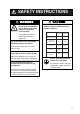
SAFETY INSTRUCTIONS WARNING ELECTRICAL SHOCK HAZARD Do not open the equipment unless totally familiar with electrical circuits and service manual. Only qualified personnel should work inside the equipment. Turn off the power at the switchboard before beginning the installation. CAUTION Observe the following compass safe distances to prevent interference to a magnetic compass: Standard Steering compass compass FA-1501 UAIS Transponder 1.2 m 0.8 m FA-1502 Monitor unit 0.45 m 0.3 m GVA-100 0.3 m 0.
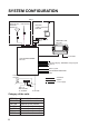
SYSTEM CONFIGURATION Either GPS antenna GSC-001 GPA-017S VHF antenna GPS/VHF combined antenna GVA-100 Distributor unit DB-1 MONITOR UNIT FA-1502 UNIVERSAL AIS MENU ENT DISP DIM NAV STATUS FA-150 PWR 12-24 VDC UAIS TRANSPONDER FA-1501 External display, NAVNET2, Pilot plug unit Sensor Alarm system PC, BEACON RECEIVER LAN Power supply PR-240 : Standard : Option : Local supply 24 VDC 100-115/ 200-230 VAC 1φ, 50/60Hz 12-24 VDC Category of the units GSC-001 GPA-017S GVA-100 FA-1501 FA-1502 DB-1 PR-
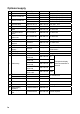
EQUIPMENT LISTS Standard supply No. Name 1 UAIS Transponder 2 Monitor Unit 3 GPS Antenna GPS/VHF Combined 4 5 6 Type FA-1501 FA-1502 GSC-001 GPA-017S GVA-100 MJ-A10SPF0012-050 CP24-00501 Code no. 000-150-216 005-955-550 Qty 1 1 CP24-00400 000-041-980 1 CP24-00101 CP24-00141 005-950-730 005-952-330 1 1 CP24-00502 005-955-560 1 FP14-02801 SP24-00101 004-366-960 - 1 1 1 Select one.
Optional supply No. Name 1 Monitor unit 2 Antenna cable set 3 Antenna cable set 4 5 Coaxial cable Mast mount fixture Right-angle antenna base L-angle antenna base Antenna base for rail mount Whip antenna Antenna fixing bracket Whip antenna AC-DC power supply Pilot plug AD-100 6 7 8 9 10 11 12 13 14 Type FA-1502 CP20-02700 CP20-02710 CP24-00300 CP24-00310 TNC-PS-3D-15 CP20-01111 Code no. 004-381-160 004-381-170 000-041-938 000-041-939 000-133-670 004-365-780 No.13-QA330 000-803-239 For GSC-001 No.
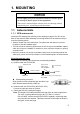
1. MOUNTING NOTICE Do not apply paint, anti-corrosive sealant or contact spray to coating or plastic parts of the equipment. Those items contain organic solvents that can damage coating and plastic parts, especially plastic connectors. 1.1 Antenna Units 1.1.1 GPS antenna unit Install the GPS antenna unit referring to the drawing on page D-5 or D-6 at the back of this manual. When selecting a mounting location for the antenna, keep in mind the following points. • Select a location out of the radar beam.
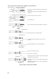
How to attach the connector N-P-8DFB for cable 8D-FB-CV Outer Sheath Armor Dimensions in millimeters. Inner Sheath Shield 50 Remove outer sheath and armor by the dimensions shown left. Expose inner sheath and shield by the dimensions shown left. 30 Cover with heat-shrink tubing and heat. Cut off insulator and core by 10mm. 10 30 Twist shield end. Slip on clamp nut, gasket and clamp as shown left. Clamp Nut Gasket Clamp (reddish brown) Aluminum Foil Fold back shield over clamp and trim.
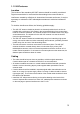
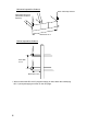
1.1.2 VHF antenna Location The location of the mandatory AIS VHF-antenna should be carefully considered. Digital communication is more sensitive than analog/voice communication to interference created by reflections in obstructions like masts and booms. It may be necessary to relocate the VHF radiotelephone antenna to minimize interference effects.
Horizontal separation distance Other VHF whip antenna Whip antenna for AIS (GPS/VHF combined antenna) More than 10 m Vertical separation distance More than 2.8 m More than 0.5 m • When coaxial cable RG-10U/Y (shipyard supply) is used, attach the coaxial plug M-P-7 (dockyard supply) as shown on the next page.
How to attach the plug M-P-7 Lay the coaxial cable and attach an M-type plug (if necessary) to the cable as follows. 1. Remove the sheath by 30 mm. 2. Bare 23 mm of the center conductor. Trim braided shield by 5 mm and tin. 3. Slide coupling ring onto cable. 4. Screw the plug assembly on the cable. 5. Solder plug assembly to braided shield through solder holes. Solder contact sleeve to conductor. 6. Screw coupling ring into plug assembly.
Mounting procedure 1. Dismount the bottom cover, cut the cable-tie inside the unit and take out the coaxial connector attached to the combined box. 2. Loosen four screws to loosen whip antenna fixture and pull out the coaxial connector coming from the combined box through the hole in the whip antenna fixture. 3. Connect the coaxial connector to the whip antenna base and wrap the junction part of the whip antenna with vulcanizing tape and then vinyl tape for waterproofing. 4.
The top of the stanchion comes into contact with the flange. Stanchion Installing distributor unit DB-1 The length of the cable between the distributor unit and transponder unit is 1 m so locate the distributor unit within 1 m from the transponder unit. Fix the distributor unit on the bulkhead, facing the cable entrance downward. Remove the lid of the distributor unit and secure the unit with two self-tapping screws.
1.2 Monitor Unit The monitor unit can be installed on a desktop or flush mounted in a panel. Install it on the chart table or near the steering place, referring to the outline drawing. When selecting a mounting location for the monitor unit, keep the following in mind: • Keep the unit out of direct sunlight. • The temperature and humidity should be moderate and stable. (Operating temperature range: -15°C to +55°C) • Locate the unit away from exhaust pipes and vents.
F type Use the optional flush mount kit OP20-29. Name Type Code No. Qty Cosmetic panel 20-016-1051 100-251-370-10 1 Self-tapping screw 5x20 000-162-609-10 4 Hexagon-head bolt M6x12 000-162-897-10 2 Spring washer M6 000-158-855-10 2 1. Prepare a cutout in the mounting location whose dimensions are 183 (W) x 92 (H) mm. 2. Attach the cosmetic panel (20-016-1051) to the unit with two hex head bolts (M6x12) and two spring washers (M6). 3.
1.3 UAIS Transponder Mount the transponder, where it is protected from rain and water splash. This unit can be installed on a bulkhead. Install it, referring to the outline drawing. When selecting a mounting location for the transponder, keep the following in mind: • Keep the transponder out of direct sunlight. • The temperature and humidity should be moderate and stable. (Operating temperature range: -15°C to +55°C) • Locate the unit away from exhaust pipes and vents.
1.4 Power Supply (option) When selecting a mounting location for the unit, keep the following in mind: • • • • • Keep the unit out away from areas subject to water splash. Locate the unit away from exhaust pipes and vents. The mounting location should be well ventilated. Mount the unit where shock and vibration are minimal. A magnetic compass will be affected if the unit is placed too close to it.
2. WIRING 2.1 Connection Connect the equipment, referring to the interconnection diagram at the back this manual. GPS Antenna GSC-001 or GPS-017S 150M-W2VN or FAB-151D GPS/VHF Conbined Antenna GVA-100 Either one 0.6 m Distributor unit DB-1 * 0.8 m * * RG-10U/Y Attached to Distributor (approx. 1m) RG-10U/Y 8D-FB-CV, 30 m/50 m: Option RG-10U/Y: Local supply : Ground is not required. Transponder unit FA-1501 BREAKER 6.3A VHF ANT GPS ANT PC Power Supply PR-240 AC DC DC IN IN OUT IV-1.
EXT ALM: Connect ship's alarm system. DISP: Connect the monitor unit. COM1 COM2 DC (-) COM3 COM4 DC (+) COM5 COM6 Internal ports of the Transponder COM1: Long range communication device (Inmarsat C, etc.) or External display (Radar, ECDIS, Pilot plug) COM2 & COM3: External display, NAVNET 2, Pilot plug COM4-COM6: GPS, Gyrocompass, Speedlog, ROT, etc. Note: A plastic sheet is placed across the cable glands of the transponder to keep out foreign material.
*: Waterproofing connectors Wrap connector with vulcanizing tape and then vinyl tape. Bind the tape end with a cable-tie. Waterproofing connector **: DPYC-2.5, TTYCS-1Q and TTYCS-4 are Japan Industry Standard cables. Use them or the equivalents. DPYC-2.5 TTYCS-1Q (Four core twisted) Armor Armor Sheath Sheath φ = 12.8 mm φ = 11.3 mm Conductor S = 2.5 mm 2 φ = 2.01 mm Conductor S = 0.75 mm2 φ = 1.11 mm TTYCS-4 (Four twisted pairs) φ = 16.3 mm Armor Sheath Shield Conductor S = 0.75 mm 2 φ = 1.
Cable connection at transponder Fabrication of cables TTYCS-4 and TTYCS-1Q L 50 Shield Remove paint by 50 mm. Cut vinyl sheath. L: Depends on equipment connected. Measure at the transponder. Expose core and fold back shield onto cable. Vinyl tape 45 6 Lay in clamp where paint was removed. Connection Wiring for WAGO connector Press downward. Terminal opener Wire Twist WAGO connector Procedures 1. Twist the cores. 2. Press the terminal opener downward. 3. Insert the wire to hole. 4.
Fabrication of power cable DPYC-2.5 50 mm Armor Vinyl sheath 6 to7 mm 40 mm: Peel paint. Taping Clamp here by cable clamp.
2.2 Changing Ship’s Mains Specifications The power supply PR-240 is shipped ready for connection to a 200-230 VAC ship’s mains. If the ship’s mains is 100 VAC – 115 VAC, change the tap connection and terminal board connection as below. Attach label supplied as accessories to the punch mark on the front panel according to the ship’s mains.
3. SETTING AND ADJUSTMENT After installing the equipment, set up the own ship’s static information (MMSI, IMO number, ship’s name, call sign, type of ship and GPS antenna position). Also, set up the I/O ports. 3.1 Setting MMSI, IMO No., Name and Call Sign 1. Press the [MENU] key to open the main menu. [MENU] MSG SENSOR STATUS INTERNAL GPS USER SETTINGS INITIAL SETTINGS CHANNEL SETTINGS DIAGNOSTICS 2. Press ▼ on the cursor pad to choose INITIAL SETTINGS and press the [ENT] key.
4. SET MMSI is selected; press the [ENT] key to display the SET MMSI window. [SET MMSI] MMSI: 000000000 IMO NO: 000000000 NAME: C. SIN: QUIT [MENU] SET MMSI window 5. MMSI is selected; press the [ENT] key. By using the cursor pad, enter ship’s MMSI (Maritime Mobile Service Identity) in nine digits. To set value, press ▲ or ▼ key and to change the digit, press ◄ or ► key. 6. Press the [ENT] key and the IMO NO is selected. 7. Press the [ENT] key and enter ship’s IMO number in nine digits.
3.2 Setting GPS Antenna Position 1. Open the INITIAL SETTINGS window, referring to page 18. 2. Press ▲ or ▼ key to choose SET INT ANT POS. and press the [ENT] key. [SET INT ANT POS.] A B A: B: C: D: 0m 0m 0m 0m C D QUIT[MENU] SET INT ANT POS. sub-menu (Data entry) 3. Press the [ENT] key again. 4. Enter distance for location “A” of FA-150 GPS antenna by using the cursor pad and press the [ENT] key. A: Distance from bow to GPS antenna position, setting range: 0-511 m 5.
3.3 Setting Ship Type 1. In the INITIAL SETTINGS window, press the ▲ or ▼ key to choose the SET SHIP TYPE and press the [ENT] key. [SET SHIP TYPE] TYPE NO : 0* * * * * TYPE DETAIL * * * * NOT AVAILABLE 2. Press the [ENT] key and set number for ship type by using ▲ or ▼ key, referring to the table below. Table: Ship type No.
2. SET COM PORT is selected; press the [ENT] key. 3. Select an appropriate port among COM1, COM2, COM3, COM4, COM5 and COM6. If you choose COM1 for example, do as follows. 4. Press the [ENT] key to display the COM1 setting window. [SET COM1] MODE : LONG RANGE SPEED: IEC 61162-2 QUIT [MENU] 5. Press the [ENT] key again to display the MODE setting window. [SET COM1] MODE : LONG RANGE SPEED: LONG RANGE EXT DISPLAY DISABLE QUIT [MENU] 6. Press ▲ or ▼ to choose the device connected and press the [ENT] key.
The table below shows the ports and corresponding items to be set.
Priority setup 1. Press ▲ or ▼ to choose SET PRIORITY at the SET I/O PORT sub-menu and press the [ENT] key. [SET PRIORITY] L/L, COG, SOG HDG ROT QUIT [MENU] PRIORITY menu 2. "L/L, COG, SOG" is selected; press the [ENT] key. [SET L/L, COG, SOG] COM4: 1 COM5: 2 COM6: 3 QUIT [MENU] 3. COM4 is selected; press the [ENT] key to display the setting window. 1 2 3 4. Choose the priority level for the COM4 port (position, course over ground and speed over ground data) and press the [ENT] key.
4. ATTACHING LAN KIT (OPTION) To connect to PC network or NAVNET 3D network, the optional LAN kit is required. Name: LAN kit Type: OP24-8 Code no.: 005-956-020 Name 1 NET100 board 2 Hex. spacer Code no. 008-535-840 000-801-678 Qty 1 4 Remark 03P9332 Attaching 1. Dismount the bottom cover. 2. Attach NET100 board 03P9332 to the 24P0035 board, referring to the figure shown below. Use screws removed at lidt figure.
Setting LAN port for PC network 1. Press the [MENU] key, choose INITIAL SETTING, enter password, choose SET I/O PORT and press the [ENT] key to show the SET I/O PORT sub menu. 2. Press ▲ or ▼ to choose SET LAN PORT and press the [ENT] key. [SET LAN PORT] MODE : STANDARD IP ADDRESS 172. 031. 024. 001 SUB NET MASK 255. 255. 000. 000 PORT NO. : 10000 QUIT [MENU] 3. Press the [ENT] key to show the mode selecting window. 4. Press ▲ or ▼ to choose suitable mode and press the [ENT] key.
4. Press the [ENT] key, enter sub net mask in the SUB NET MASK field and press the [ENT] key. (Setting range: 000.000.000.000 to 255.255.255.255) 5. Press the [ENT] key, enter port number in the NAVNET PORT NO. field and press the [ENT] key. (Setting range: 10000 to 30000) 6. Press▼ to show next page. [SET LAN PORT] 2/2 GATEWAY ADDRESS 000. 000. 000. 000 HOST NAME : AISO AISOUTPUT : CONTINUOUS GPSOUTPUT : AUTO ZDAOUTPUT : AUTO 7.
5. IEC 61162-1/2 DATA SENTENCES IEC 61162-1/2 format data is input or output from the data port COM1-COM6. The table below shows the input/output data specifications. Transponder Port Menu setting Input/Output LONG RANGE Input/Output* EXT DISPLAY Input/Output* COM2 EXT DISPLAY Input/Output* COM3 EXT DISPLAY Input/Output* SENSOR Input* EXT DISPLAY Input/Output* COM5 SENSOR Input* COM6 SENSOR Input* COM1 COM4 28 Data format IEC61162-2 (38.
Input data/Sentences Sentence (Priority) ABM ACA ACK AIR BBM VSD LRI LRF DTM GNS>GLL>GGA>RMC VBW>RMC>VTG>OSD RMC>VTG>OSD HDT>OSD>AD-10 format GBS ROT>Calculated value SSD Contents Addressed binary and safety related message AIS regional channel assignment message Acknowledge alarm AIS interrogation request UAIS broadcast binary message UAIS voyage static data Long Range interrogation Long Range function Datum reference Position Speed over ground Course over ground Heading GNSS satellite fault detection Rat
5'.( 6#22+0) 5%4'9 㩎㩡㩇㩊㨹㩕㩩㩧㩒㩆㩨 ޓ㩆㨷 ฬޓޓ⒓ 0#/' ⇛ޓޓ࿑ 176.+0' For FA-1501 %1&' 01 : 575 ဳฬ㧛ⷙᩰ &'5%4+26+105 ᢙ㊂ 3 6; %2 6;2' ↪ㅜ㧛⠨ 4'/#4-5 #% : 㧲㨁㧾㨁㧺㧻ޓ㧱㧸㧱㧯㨀㧾㧵㧯ޓ㧯㧻ޓ㧚㧘㧸㨀㧰 㧔⇛࿑ߩኸᴺߪޔෳ⠨୯ߢߔ&ޓޕ+/'05+105 +0 &4#9+0) (14 4'('4'0%' 10.; 㧕 #% : ဳᑼ 㩄㨺㩎㩨⇟ภ߇㧞Ბߩ႐วޔਅᲑࠃࠅᲑߦઍࠊࠆㆊᷰᦼຠߢࠅޔ߅ߥޓޕߔ߹ߡߞ߇߆ࠄߜߤޔຠ⾰ߪᄌࠊࠅ߹ߖ ࠎޕ 691 6;2'5 #0& %1&'5 /#; $' .+56'& (14 #0 +6'/ 6*' .19'4 241&7%6 /#; $' 5*+22'& +0 2.#%' 1( 6*' 722'4 241&7%6 37#.
+056#..#6+10 /#6'4+#.5 70+6 1 7 6 .
⇟ ภ 01 ⇛ޓޓ࿑ 176.+0' For DB-1 ᢙ㊂ 3 6; ## : ↪ㅜ㧛⠨ 4'/#4-5 ## : 㧲㨁㧾㨁㧺㧻ޓ㧱㧸㧱㧯㨀㧾㧵㧯ޓ㧯㧻ޓ㧚㧘㧸㨀㧰 %1&' 01 : 575 㩆㨷 ဳฬ㧛ⷙᩰ &'5%4+26+105 %2 6;2' 㧔⇛࿑ߩኸᴺߪޔෳ⠨୯ߢߔ&ޓޕ+/'05+105 +0 &4#9+0) (14 4'('4'0%' 10.; 㧕 5'.( 6#22+0) 5%4'9 㩏㩗㩨㩊㨹㩕㩩㩧㩒㩆㩨 ฬޓޓ⒓ 0#/' +056#..#6+10 /#6'4+#.5 Ꮏ᧚ᢱ %1&' 01 A-5 ⇟ ภ 01 %18'4 ⼔㩀㩔㩨㨺 ⇛ޓޓ࿑ 176.
(75' 㩕㨷㨺㩇㩨 ()$1 # # #% 8 ()$ # 8 # 2$( 2'4 8'5 #% : ဳᑼ 㩄㨺㩎㩨⇟ภ߇㧞Ბߩ႐วޔਅᲑࠃࠅᲑߦઍࠊࠆㆊᷰᦼຠߢࠅޔ߅ߥޓޕߔ߹ߡߞ߇߆ࠄߜߤޔຠ⾰ߪᄌ ࠊࠅ߹ߖࠎޕ 691 6;2'5 #0& %1&'5 /#; $' .+56'& (14 #0 +6'/ 6*' .19'4 241&7%6 /#; $' 5*+22'& +0 2.#%' 1( 6*' 722'4 241&7%6 37#.+6; +5 6*' 5#/' 5'65 2'4 8'55'. $1: 01 2 4'/#4-5 %1&' 01 #% : 52#4' 㧔⇛࿑ߩኸᴺߪޔෳ⠨୯ߢߔ&ޓޕ+/'05+105 +0 &4#9+0)(ޓ14 4'('4'0%' 10.
CP20-00310 (000-041-939) CP20-00300 (000-041-938) Antenna Cable Set A-9
Y.
Y.
Y.
D-4 Y.
D-5 Mar,27'07 R.
D-6 May 20 '03
D-7 Feb.
Jan.
Apr.20'07 R.
D-10 Feb.
D-11 Nov.
Oct.
D-13 Y.
1 2 150M-W2VN *2 OR FAB-151D GSC-001 VHFアンテナ VHF ANTENNA 150M-W2VN *2 OR FAB-151D GPSアンテナ GPS ANTENNA GPA-017S OR GSC-001 0.2m(GPA-017S) 0.