
Operator's Manual


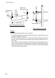
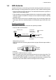

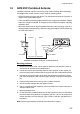
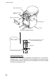
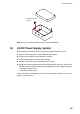
Table Of Contents
- IMPORTANT NOTICES
- SAFETY INSTRUCTIONS
- TABLE OF CONTENTS
- FOREWORD
- SYSTEM CONFIGURATIONS
- 1. INSTALLATION
- 2. OPERATION
- 3. MAINTENANCE,TROUBLESHOOTING
- APPENDIX 1 MENU TREE
- APPENDIX 2 VHF CHANNEL LISTS
- APPENDIX 3 PARTS LIST,LOCATIONS
- APPENDIX 4 DIGITAL INTERFACE
- SPECIFICATIONS
- PACKING LIST
- OUTLINE DRAWINGS
- INTERCONNECTION DIAGRAM
- INDEX
- Declaration of conformity
1. INSTALLATION
1-5
1.4 GPS Antenna
Install the GPS antenna unit referring to the outline drawing at the back of this manual.
When selecting a mounting location for the antenna, keep in mind the following points.
• Select a location out of the radar beam. The radar beam will obstruct or prevent re-
ception of the GPS satellite signal.
• There should be no interfering object within the line-of-sight to the satellites. Objects
within line-of-sight to a satellite, for example, a mast, may block reception or prolong
acquisition time.
• Mount the antenna unit as high as possible to keep it free of interfering objects and
water spray, which can interrupt reception of GPS satellite signal if the water freez-
es.
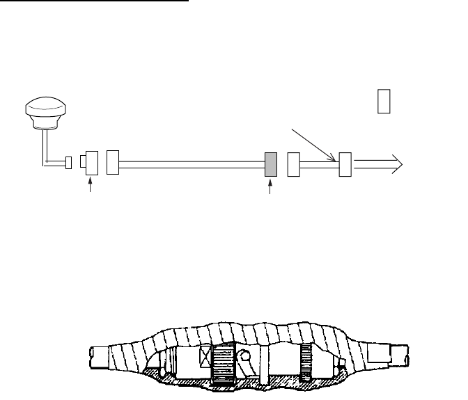
Extending antenna cable
Three types of antenna cable extensions are optionally available.
• Antenna cable set CP20-02700
Waterproofing connector
Wrap connector with vulcanizing tape and then vinyl tape. Bind the tape end with a
cable-tie.
• Antenna cable set CP20-02710 (8D-FB-CV, 50 m)
• Connect the cable the same as 1) above.
Note: The length of this cable should be less than 20 m to prevent signal loss. The
coax. coupling cable assy.(type: NJ-TP-3DXV-1, code no. 000-123-809), coaxial
connector (N-P-8DFB; supplied), vulcanizing tape and vinyl tape are required. Fab-
ricate both ends of the cable as shown in the figure on the next page.
Antenna Unit
Antenna Cable
30m 1 m
Fabricate locally. (See next page.)
N-P-8DFB
FA-50
: Connector
Conversion
Cable Assy.
NJ-TP-3DXV-1
TNCP-NJ
0.6m