Installation Manual COLOR LCD SOUNDER FCV-1200L/FCV-1200LM SAFETY INSTRUCTIONS .......................................................................... i SYSTEM CONFIGURATION .................................................................... iii EQUIPMENT LISTS .................................................................................. v 1. MOUNTING 1.1 1.2 1.3 1.4 1.5 1.6 Monitor Unit, Control Unit .........................................................................................
The paper used in this manual is elemental chlorine free. ・FURUNO Authorized Distributor/Dealer 9-52 Ashihara-cho, Nishinomiya, 662-8580, JAPAN Telephone : +81-(0)798-65-2111 Fax : +81-(0)798-65-4200 All rights reserved. Printed in Japan A : APR . 2000 T1 : JUN . 18, 2007 Pub. No.
SAFETY INSTRUCTIONS WARNING WARNING ELECTRICAL SHOCK HAZARD Install the transducer according to the installation instructions. Do not open the equipment unless totally familiar with electrical circuits and service manual. Failure to install the transducer correctly may result in water leakage and damage to the ship's hull. Only qualified personnel should work inside the equipment. For wooden or FRP vessel using a steel tank, attach a zinc plate to the hull to prevent electrolytic corrosion.
CAUTION CAUTION The transducer cable must he handled carefully, following the guidelines below. Ground the equipment to prevent mutual interference. • Keep fuels and oils away from the cable. • Locate the cable where it will not be damaged. • The cable sheath is made of chlorophrene or polychloride vinyl, which are easily by damaged plastic solvents such as toulene. Locate the cable well away from plastic solvents.
SYSTEM CONFIGURATION Standard type MONITOR UNIT MU-101C CONTROL UNIT CV-1201: Portrait type CV-1202: Landscape type Navigator *4 NMEA 0183 External Monitor Interface Unit IF-8000 PROCESSOR UNIT CV-1203 (FCV-1200L) CV-1203M (FCV-1200LM) Water Temp. Sensor (T-02MSB, etc.
Blackbox type External Monitor Navigator NMEA 0183 MONITOR UNIT MU-101C CONTROL UNIT CV-1201: Portrait type CV-1202: Landscape type *4 Interface Unit IF-8000 Interface Unit IF-8000 PROCESSOR UNIT CV-1203 (FCV-1200L) CV-1203M (FCV-1200LM) Water Temp. Sensor (T-02MSB, etc.
EQUIPMENT LISTS Standard supply Name Monitor Unit Processor Unit Spare Parts Type Code No.
Blackbox type Name Type Code No. Qty CV-1201-E-15 − 1.5 m cable, portrait type CV-1201-E-50 − 5 m cable, portrait type Control Unit Processor Unit 1 CV-1202-E-15 − 1.
Optional equipment (con’t) Rectifier RU-1746B-2 Cable MJ-A6SPF0012-050 000-134-424 1 6 pin-6 pin, 5 m, for navigator MJ-A6SPF0012-100 000-133-817 1 6 pin-6 pin, 10 m, for navigator MJ-A6SPF0011-050 000-132-244 1 6 pin-4 pin, 5 m, for navigator MJ-A6SPF0011-100 000-132-336 1 6 pin-4 pin, 10 m, for navigator MJ-A10SPF0002-0015 000-142-879 1 10 pin-10 pin, 0.15 m, for control unit MJ-A10SPF0002-050 000-131-411 1 10 pin-10 pin, 5 m, for control unit 06S4078*1.
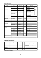
Available transducers 1 kW transducer Frequency (kHz) Hull Material Steel 15/45 FRP Steel FRP Steel 15/50 FRP Steel FRP Steel 15/68 FRP Steel 15/88 FRP Steel 15/200 FRP Steel 28/45 FRP Steel FRP Steel 28/50 FRP Steel FRP Steel 28/68 FRP Steel 28/88 FRP Steel 28/200 FRP Steel 45/88 FRP Transducer Thru-Hull Pipe Tank 15F-4S 45F-3H 15F-4S 50B-6/6B 15F-4S 50B-9B 15F-4S 50F-8G 15F-4S 68F-8H 15F-4S 88B-8 15F-4S 200B-5S 28F-8 45F-3H 28F-8 50B-6/6B 28F-8 50B-9B TWB-6000 (2) T-656 28F-8 50F-8G 28F-8 68F-8
1 kW transducer (con’t) Frequency (kHz) Hull Material Steel 45/200 FRP Steel FRP Steel 50/88 FRP Steel FRP Steel FRP Steel FRP Steel 50/200 FRP Transducer Thru-Hull Pipe 45F-3H 200B-5S 50B-6/6B 88B-8 50B-9B 88B-8 TWB-6000 (2) T-658 50F-8G 88B-8 50B-6/6B 200B-5S 50B-9B 200B-5S 50F-8G 200B-5S Steel 50/200-1T FRP Steel 50/200-1ST FRP Steel FRP Steel 50/400 FRP Steel FRP Steel 68/200 FRP 88/200 Steel FRP Tank 50B-6/6B 400B-52 50B-9B 400B-52 50F-8G 400B-52 68F-8H 200B-5S 88B-8 200B-5S ix
2 kW transducer Frequency (kHz) Hull Material Steel 15/45 FRP 15/50 15/68 Steel FRP Steel FRP Steel 15/88 FRP Steel 15/200 FRP Steel 28/45 FRP Steel 28/50 FRP Steel 28/68 FRP Steel 28/88 FRP Steel 28/200 FRP Steel 45/88 FRP 45/200 Steel FRP Steel 50/88 FRP Steel 50/200 FRP Steel 68/200 FRP 88/200 Steel FRP Transducer Thru-Hull Pipe Tank 15F-10 45F-6H 15F-10 50B-12 TFB-7000 (2) T-627 15F-10 68F-30H 15F-10 88B-10 15F-10 200B-8/8B/8N TFB-7000 (2) T-629 TRB-1100 (2) T-629-F TFB-7000 (2) T-632 TRB-
3 kW transducer *: 5 kW transducer.
3 kW transducer (con’t) *: 5 kW transducer.
1 kW/2 kW transducer Output (W) Frequency (kHz) Hull Material Steel 15/45 FRP Steel 15/50 FRP Steel 15/68 FRP Steel 15/88 FRP Steel 15/200 FRP Steel 28/45 FRP Transducer Thru-hull Pipe Tank 15F-4S 45F-6H TFB-7000 (2) T-626 15F-4S 50B-12 TRB-1100 (2) T-626-F 15F-4S 68F-30H TWB-6000 (2) T-628 15F-4S 88B-10 TRB-1100 (2) T-628-F 15F-4S 200B-8/8B/8N TWB-6000 (2) T-631 TRB-1100 (2) T-631-F 28F-8 45F-6H 1 k/2 k Steel 28/50 FRP Steel 28/68 FRP Steel 28/88 FRP Steel 28/200 FRP Steel 45/88 FRP Steel 4
1 kW/2 kW transducer (con’t) Output (W) Frequency (kHz) Hull Material Steel FRP Steel 50/88 FRP Steel FRP Steel FRP Transducer Thru-hull Pipe Tank 50B-6/6B 88B-10 50B-9B 88B-10 TFB-7000 (2) T-636 50F-8G 88B-10 TRB-1100 (2) T-636-F 50B-6/6B 200B-8/8B/8N 1 k/2 k Steel 50/200 FRP Steel FRP Steel 68/200 FRP Steel 88/200 FRP 50B-9 200B-8/8B/8N 50F-8G 200B-8/8B/8N TWB-6000 (2) T-658 TFB-7000 (2) T-638 TRB-1000 (2) T-638-F 68F-8H 200B-8/8B/8N 88B-8 200B-8/8B/8N xiv TWB-6000 (2) T-659
1 kW/3 kW transducer *: 5 kW transducer.
1 kW/3 kW transducer (con’t) *: 5 kW transducer.
2 kW/3 kW transducer *: 5 kW transducer.
2 kW/3 kW transducer (con’t) *: 5 kW transducer.
3 kW/2 kW transducer *: 5 kW transducer.
This page is intentionally left blank.
1. MOUNTING 1.1 Monitor Unit, Control Unit The monitor and control units can be installed as one unit (unibody) or two separate units. The optional “separate monitor unit installation kit” is necessary when installing them as separate units. Further, these units can be mounted in a panel (requires optional flush mount kit), together or separately. See the outline drawings at the back of this manual for details. Mounting considerations • Locate the units out of direct sunlight.
For portrait-type unibody monitor unit a) Pass the signal cable (connects between interface unit and display unit) through the slot in the hanger and then connect the cable to the display unit. HANGER Signal Cable Slot Figure 1-2 Hanger b) Fasten the hanger at the rear of the display unit with four binding screws (M4X10).
Display unit for separate type, blackbox type (vertical-type control unit) 1. Dismount the coupling place from the rear of the display unit to separate display unit from control unit. 2. Pass the signal cable (connects between interface unit and display unit) through the slot in the hanger and then connect the cable to the display unit. HANGER Signal Cable Slot Figure 1-5 Monitor unit, rear view 3. Attach the hanger at the rear of the display unit with four binding screws (M4X10).
Hanger (rear view) 1 1 2 4 3 2 4 3 Figure 1-7 Hanger, rear view 3. Coat threads of upset screws (M6X16, 2 pcs.) used to fasten hanger to mounting base. 4. Fasten the hanger (or display unit) to the mounting base with two upset screws. (Use the upper holes to tilt the display unit 20°; lower holes to tilt it 9°.) se these holes to tilt monitor unit 20˚. MOUNTING BASE se these holes to tilt monitor unit 9˚.
Hex-head screws Mounting fixture location changes with monitor orientation. Mounting fixture Figure 1-9 How to flush mount unibody type monitor unit 3. Fasten the monitor unit to the mounting location with six self-tapping screws. Separate monitor unit flush mount kit Separate monitor unit flush mount kit: Type OP06-17, Code no. 006-556-310 Name Type Code No.
Separate control unit flush mount kit Control unit flush mount kit OP06-18 (Code no. 006-556-320) Separate installation kit OP02-83-1.5 (Code no. 001-413-600) Separate installation kit OP02-83-5 (Code no. 001-413-610) Name Type Code No. Qty Mounting Fixture 06-021-2101 100-279-731 1 Self-tapping Screw 5×20 000-162-609-10 4 Hex-head Screw M4×12 000-162-939-10 2 MJ-A10SPF002-015 000-142-878 MJ-A10SPF002-050 000-131-411 Cable Assy. 1 Remarks 1.5 m OP02-83 only 5m 1.
Blackbox type Supply monitor and interconnection cable (D-sub connector, three rows of 15 pins, max. length 15 m) locally. The monitor connects to the interface unit, and should satisfy the specifications shown below. • VGA type • Analog RGB, 0.7 Vpp, positive polarity • TLL level H, V, negative polarity Control unit for blackbox type The control unit comes in two types: portrait and landscape. The landscape-type control unit can be installed on a desktop or flush mounted in a panel.
1.2 Processor Unit There are two types of Processor Units: CV-1203 (FCV-1200L) and CV-1203M (FCV-1203LM). With the EXIF Board Assy. (standard on FCV-1200LM, optional on FCV-1200L) external equipment such as an echosounder interface, switch box, etc. can be connected. The unit can be mounted on the deck, a desktop or on a bulkhead. Select a mounting location considering the points below. • Locate the unit out of direct sunlight. • Select a location where temperature and humidity are moderate and stable.
1.3 Interface Unit The Interface Unit IF-8000 is supplied with the blackbox-type system, and is optional with the standard type system. It can be mounted on the deck, a desktop or a bulkhead. Select a mounting location for it considering the following: • Locate the unit away from areas subject to water splash. • The length of the cable to processor unit is 10 max. • Leave sufficient space around the unit for maintenance and servicing.
Thru-hull mount water temperature sensor T-02MSB, T-03MSB Select a suitable mounting location considering the following points: • Select a mid-boat flat position. The sensor does not have to be installed perfectly perpendicular; however, the location should not be such that the transducer may be damaged when the boat is dry-docked. • Locate away from equipment which gives off heat. • Locate away from drain pipes. • Select a location where vibration is minimal.
2. WIRING Refer to the interconnection diagram at the back of this manual for detailed information. If the D-sub connector (used with monitor unit, processor unit, interface unit) is too large to pass through a hole, remove the connector cover. Cover wiring with vinyl tape and pass cable through hole. This will permit passing of the cable through a hole of 30 mm diameter.
Blackbox-type FCV-1200L CONTROL UNIT CV-1201: Portrait type CV-1202: Landscape type MONITOR UNIT MU-101C External Monitor 06S4078 (1.5m/ 5m/10m) NMEA 0183 Navigator Interface Unit IF-8000 06S4078 (1.5m/5m/10m) C MJ-A10SPF0002-015 MJ-A10SPF0002-050 *4 B 06S4078 (1.5m/5m/10m) A PROCESSOR UNIT CV-1203 Interface Unit IF-8000 Water Temp. Sensor (T-02MSB, etc.) External Monitor Ship's Mains 12-24 VDC Net Sonde FNZ-18 DPYCYS-2.
Standard-type FCV-1200LM CONTROL UNIT CV-1201: Portrait type CV-1202: Landscape type MONITOR UNIT MU-101C NMEA 0183 Navigator *2 *4 06S4078 *1.5m/5m/10m* External Monitor B 06S4078 (1.5m/5m/10m) Water Temp. Sensor (T-02MSB, etc.) 06S4078(1.5m/5m/10m) PROCESSOR UNIT CV-1203M TEMP Ship's Mains 12-24 VDC DPYCYS-2.
Blackbox-type FCV-1200LM CONTROL UNIT CV-1201: Portrait type CV-1202: Landscape type MONITOR UNIT MU-101C External Monitor MJ-A10SPF0002-015 MJ-A10SPF0002-050 06S4078(1.
2.1 Wiring Standard Equipment Transducer (FCV-1200L only) Separate the transducer cable well away from power cables to prevent interference. Connect the cable to the transducer connector at the rear of the processor unit. Fabricate the cable as below. Shield Shield Foam 71TS-10-1 Cable Connector Cable Clamp Figure 2-5 Fabrication of transducer cable Note: For connection of dual-frequency transducer, use cable assy. NCS255AD-254P-L500 (option).
Power cable This video sounder is designed to be powered with 12-24 VDC power. To prevent power loss, use power cable DPYCYS-2.0 (or equivalent) or equivalent. The armor should lie within the connector case. Confirm polarity when connecting pins.
Use a monitor cable (max. length 15 m) to connect a commercial monitor. A D-sub 15P connector with three rows of pins is required for connection at the interface unit. The monitor must satisfy the following requirements: VGA type Analog RGB, 0.7Vpp, positive polarity TTL level H, V, negative polarity Note 1: Two interface units may be connected. Note 2: When connecting the Monitor Unit MC-101C or an interface unit to the terminal DATA/VIDEO OUT its connector will touch the connector of DATA/VIDEO IN.
2.2 Wiring Optional Equipment Navigator Use cable type MJ-A6SPF0011/0012 (option) to connect the navigator to the NMEA connector on the standard LCD monitor unit or Interface Unit in case of blackbox system. For detailed information see the interconnection diagram at the back of this manual. Water temperature sensor T-02MSB, T-02MTB, T-03MSB Connect the water temperature sensor cable to the TEMP connector on the processor unit.
EXIF board assy. The EXIF board assy. (type OP02-81, code no. 000-012-463), installed inside the processor unit CV-1203, is necessary when connecting a telesounder (on sister ship and master ship), transceiver or other video sounder to the FCV-1200L. Below are the contents of the EXIF board assy. kit. For connection cable use type S-02-6-10 (24P, 10 m, Code No. 002-962-030). Name EXIF Assy. Pan Head Screw SRCN Connector Type OP02-81 M4×10 SRCN6A25-24P Code No.
2.
3. INITIAL SETTINGS This section provides the information necessary for initial setup of the equipment. First turn on the power and set display language. For the FCV-1200L, enter transducer used, by model number (FURUNO transducer only) or by specifications. For either model, execute other procedures as applicable. 3.1 Language Setting 1. Turn on the power. The following display appears. Note: The picture on your set may be turned 90°. Picture orientation may be corrected at section 3.2.
3.2 Display Type If your picture is turned 90° do the following: 1. Press any key to show the installation main menu. XDCR SETTING INSTALLATION DEMO XDCR SELECT : XDCR TYPE [HIGH] FREQ TRANSDUCER PWR REDUCTION OUTPUT POWER SUPPLY VOLT : : : : : --- kHz ----OFF -- kW -- V [LOW] FREQ TRANSDUCER PWR REDUCTION OUTPUT POWER SUPPLY VOLT : : : : : --- kHz ----OFF -- kW -- V [-/+]: Change setting, Turn OFF to exit Figure 3-2 Installation main menu 2. Press [+] to selection INSTALLATION.
3. Press [ ] to select MONITOR TYPE, and then press [+] to open the dialog box. PORTRAIT LANDSCAPE 4. Use [+] or [-] to select appropriate monitor type, and then press [+] to close the dialog box. 5. Turn off the power to change picture orientation. 3.3 Transducer Data (FCV-1200L only) This paragraph provides information necessary for entering transducer data. You enter transducer data by either transducer model number (for FURUNO transducer, page 3-4) or specification (page 3-5).
Entering transducer data by transducer model number Note 1: If you are continuing from paragraph 3.1 go to step 2. Note 2: If you have already entered transducer settings and want to reconfirm them turn on the power while pressing any key. 1. Turn on the power. 2. Press any key to show the following menu.
MAX 1/2 1/4 1/8 1/16 MIN 8. Press [+] or [-] to select appropriate power, and then press [ ] or [ ] to close the dialog box. Normally set to MAX. MIN means transmission power less than 1W. 9. Follow steps 1-6 to enter model number of other transducer if installed. Note: For dual-frequency transducer, enter both high and low frequencies and set the same transducer model number for both high and low frequencies. 10. Confirm settings and turn off the power.
5. Do the following for both the high and low frequency transducers, or whichever transducer is installed. a) Press [ ] to select [HIGH] FREQ or [LOW] FREQ, and then press [+] to open the dialog box. --- kHz b) Press [+] or [-] to enter transducer frequency, and then press [ ] or [ ] to close the dialog box. c) Press [ ] to select SUPPLY VOLT, and then press [+] to open the dialog box. --- V d) Press [+] or [-] to enter transducer supply voltage, and then press [ ] or [ ] to close the dialog box.
3.4 Adjustment for Transceiver Unit, Video Sounder, Telesounder, Picture Recorder This section provides the settings necessary when connecting a Transceiver Unit (ETR-5D, ETR-10D, etc.), Color Video Sounder, Telesounder (TS-30/507000/8000) or the Picture Recorder MT-12. Note 1: For the FCV-1200L, first install the EXIF board assy. See page 2-7. Note 2: For the FCV-1200LM, only a master ship’s telesounder can be connected.
4. Press [ ] to select E/S DRAFT SETTING, and then press [+] to open that menu. DISP ALM TX/RX USER-1/2 SYSTEM E/S DRAFT SETTING XDCR CONNECT TX POWER DRAFT FREQ CHOICE XDCR CONNECT TX POWER DRAFT FREQ CHOICE : INTERNAL : MAX : +0.0 ft (-15~+90) : ***kHz E/S SIG OUT KP SETTING : OFF : INTERNAL : INTERNAL : MAX : +0.0 ft (-15~+90) : **kHz Select transducer connected. [-/+]: Change set, [EXIT (knob)]: Exit Figure 3-7 E/S DRAFT SETTING menu 5.
For transceiver unit 1. Do the following for both high and low frequencies, or whichever is installed. a) Use [ ] or [ ] to select DRAFT and press [+] to open the dialog box. +0.0 b) Use [+] or [-] to enter ship’s draft, and then press [ ] or [ ] to close the dialog box. 2. Press [ ] to select E/S SIG OUT, and then press [+] to open the dialog box. OFF LF HF LF/HF 3. Select OFF, and then press [ ] or [ ] to close the dialog box. 4. Turn the [FUNCTION] switch to the EXIT position to quit.
9. Press [+] to select EXTERNAL, and then press [ ] or [ ] to close the dialog box. 10. Turn the [FUNCTION] switch to the EXIT position to quit. Telesounder The FCV-1200LM can only be connected to a telesounder on board a master ship and the FCV-1200L to a telesounder on board a master ship or sister ship. 1. Turn on the power. 2. Turn the [FUNCTION] switch to the MENU position. 3. Press [ ] and [+] to select SYSTEM at the top of the screen. 4.
5. Do the following for both the high and low frequencies, or whichever is installed. a) Use [ ] or [ ] to select DRAFT, and then press [+] to open the dialog box. +0.0 b) Enter value measured at step 2 with [+] or [-], and then press [ ] or [ ] to close the dialog box. Final adjustment (master ship and sister ship) 1. Observer the picture from the sister ship and master ship.
3.5 Water Temperature Sensor Setting If a water temperature sensor is connected set up as follows: 1. Turn on the power and turn the [FUNCTION] switch to the MENU position. 2. Press [ ] and [+] to select SYSTEM at the top of the screen. 3. Press [ ] to select TEMP SETTING, and then press [+] to open that menu. DISP ALM TX/RX USER-1/2 SYSTEM TEMP SETTING TEMP INPUT TEMP ADJUST : SENSOR : +0.0˚F (-20~+20) TEMP READOUT : ON TEMP GRAPH TEMP COLOR : OFF : STD Select temperature sensor.
c) Use [+] or [-] to enter the difference found in b) above. For example, if the indication of the FCV-1200L is +5° higher than the actual value, enter –5 (degrees). d) Press [ ] or [ ] to close the dialog box. 7. Press [ ] to select TEMP READOUT, and then press [+] to open the dialog box. OFF ON 8. Use [-] or [+] to turn the water temperature indication OFF or ON (default setting) respectively, and then press [ ] or [ ] to close the dialog box. 9.
3.6 Net Sonde Setting Follow the procedure below when a Net Sonde is connected to the video sounder. 1. Turn on the power and turn the [FUNCTION] switch to the MENU position. 2. Press [ ] and [+] to select SYSTEM at the top of the screen. 3. Press [ ] to select NET SONDE SETTING, and then press [+] to open that menu. DISP ALM TX/RX USER-1/2 SYSTEM NET SONDE SETTING SONDE MARK : OFF COLOR : 1 SONDE GRAPH GRAPH MODE GRAPH WIDTH GRAPH RESET : OFF : SURFACE : 1/4 : NO Indication of sonde mark.
9. Press [ ] to select SONDE GRAPH, and then press [+] to open the dialog box. OFF ON 10. Use [-] or [+] to turn the graph display OFF (default setting) or ON as appropriate, and then press [ ] or [ ] to close the dialog box. 11. Press [ ] to select GRAPH MODE, and then press [+] to open the dialog box. SURFACE BOTTOM 12. Use [-] or [+] to select what temperature to use for the graph, and then press the [ ] or [ ] to close the dialog box.
3.7 Nav Data, Heading Sensor Setting Select navigator and heading sensor used as below. 1. Turn on the power and turn the [FUNCTION] switch to the MENU position. 2. Press [ ] and [+] to select SYSTEM at the top of the screen. 3. Press [ ] to select NAV DATA SETTING, and then press [+] to open that menu. (If a heading sensor is connected but not a navigator, go to step 10.) DISP ALM TX/RX USER-1/2 SYSTEM NAV DATA SETTING SPEED INFO : OFF NMEA VERSION : Ver 2.
8. Press [ ] to select NAV DATA, and then press [+] to open the dialog box. LC LA DECCA GPS DR AUTO 9. Use [-] or [+] to select type of navigator connected, and then press [ ] or [ ] to close the dialog box. AUTO (default setting) selects a navigator in the order of GPS, Loran C, Loran A, Decca, DR (Dead Reckoning). 10. Press [ ] to select COURSE, and then press [+] to open the dialog box. TRUE MAG 11.
3.8 Stabilization (heaving compensation) The stabilization feature is available with connection of a satellite compass (SC-50/SC-110) to the NMEA port and functions to compensate for ship's heaving. Set NMEA output from the satellite compass as below and follow the accompanying procedure to compensate for heaving. Output format: IEC ED1 Sentence: ATT, HVE, VTG, GLL Baud rate: 4800 bps Interval: 200 ms 1. Turn on the power. 2. Set the FUNCTION control to the MENU position. DISP ALM TX/RX USER-1/2 SYSTEM 3.
3.9 Propagation Velocity This section provides the information for adjustment of propagation velocity. Normally, no adjustment is necessary, however if the depth indication is wrong, lower or raise propagation velocity as appropriate. 1. Turn on the power while pressing any key to show the installation main menu. 2. Press [+] or [-] to select the INSTALLATION menu. XDCR SETTING INSTALLATION DEMO MONITOR TYPE : LANDSCAPE SOUND SPEED : 1500.
3.10 Demonstration Mode The demonstration mode provides a simulated video sounder picture. Connection of the transducer is not necessary. All controls are operational. 1. Turn on the power while pressing any key to display the installation main menu. 2. Press [+] to select DEMO. XDCR SETTING INSTALLATION DEMO DEMO MODE : OFF [-/+]: Change setting, Turn OFF to exit Figure 3-13 DEMO menu 3. Press [ ] to select DEMO MODE, and then press [+] to open the dialog box. OFF ON 4.
3.11 Restoring Default Settings The procedure below restores most default settings. The following settings are not affected: target setting, language, demo mode, monitor type (portrait, landscape), transducer settings, user color settings and user clutter settings. 1. Turn on the power and turn the [FUNCTION] switch to the MENU position. 2. Press [ ] and [+] to select SYSTEM at the top of the screen. 3. Press [ ] to select DEFAULT SETTING, and then press [+] to open that menu.
3.12 DIP Switch Setting Interface unit IF-8000 Open the cover of the IF-8000. Set DIP Switch S1 according to system configuration, referring to the illustration below.
Default setting (for linear amp) 1 2 3 4 5 6 7 8 S2 ON OFF S3 1 2 3 4 5 6 7 8 ON OFF 1 2 3 4 5 6 7 8 S1 ON OFF Setting for log amp DIP SWITCH S1 DIP SWITCH S2 1 2 3 4 5 6 7 8 1 2 3 4 5 6 7 8 DIP SWITCH S3 1 2 3 4 5 6 7 8 ON ON ON OFF OFF OFF 1: 2: 3: 4: 5: 6: 7: KP OUT L POS (Default: ON) KP OUT L NEG (Default: OFF) KP IN L POS (Default: ON) KP IN L NEG (Default: OFF LINER IN L (Default: ON) LOG IN L (Default: OFF) KP IN L 12V (OFF, Default) KP IN L 5 V (ON) 8: WL IN L 12V (OFF, Default)
APPENDIX 1 TRANSDUCER 50BL-12/50BL-24H When using the transducer 50BL-12/50BL-24H, see this appendix. Transducer, thru-hull pipe and tank list Frequency (kHz) 50/200 28/50 50/88 50/200 Hull Material Transducer Tank (Code No.) Fasten inside hull (Code No.) Fasten outside hull (Code No.
APPENDIX 2 BLT TRANSDUCERS The BLT transducer (Bolt-clamp Langevin Transducer) has large bandwidth, good sound efficiency, compact structure and is reinforced for protection against slamming. Transducer, thru-hull pipe and tank list Frequency (kHz) 28/200 38/200 50/200 28/38 28/50 38/50 28/88 38/88 AP-2 Transducer 28BL-6HR/200B-8B 38BL-9HR/200B-8B 50BL-12HR/200B-8B 28BL-12HR/38BL-15HR 28BL-12HR/50BL-24HR 38BL-15HR/50BL-24HR 28BL-12HR/88F-126H 38BL-15HR/88F-126H Hull Material Tank (Code No.
APPENDIX 2 BLT TRANSDUCERS 50/88 28/200 38/200 50/200 28/150 38/150 50/150 50BL-24HR/88-126H 28BL-12HR/200B-12H 38BL-15HR/200B-12H 50BL-24HR/200B-12H 28BL-12HR/150B-12H 38BL-15HR/150B-12H 50BL-24HR/150B-12H Steel T-682 (000-015-851) TWB-6000 (2) (000-015-207) TFB-7000 (2) (000-015-209) FRP T-682F (000-015-852) TRB-1100 (2) (000-015-219) - Steel T-683 (000-015-853) TWB-6000 (2) (000-015-207) TFB-7000 (2) (000-015-209) FRP T-683F (000-015-854) TRB-1100 (2) (000-015-219) - Steel
APPENDIX 3 TRANSDUCER 82B-35R The 82B-35R is a transducer with wide bandwidth of 65 kHz-110 kHz. It is constructed to provide protection against slamming. Transducer, thru-hull pipe and tank list Frequency (kHz) 15/88 Transducer 15F-4S/82B-35R 15F-10/82B-35R 28/88 50/88 28F-18/82B-35R 50F-8G/82B-35R 50B-12/82B-35R 88/200 82B-35R/200B-8/200B-8B /200B-8N Hull Material Tank (Code No.) Fasten inside hull (Code No.) Fasten outside hull (Code No.
A-1
A-2
A-3
A-3A
A-4
A-5
A-7
A-9
D-1
D-2
D-2A
D-2B
D-3
D-4
D-5
D-5A
D-5B
D-6
D-9 Nov.
This page is intentionally left blank.
*3 CONT DATA/VIDEO IN XM2A-2501 1 TRXTD_A R 1 2 TRXTD_B G 2 3 CONTD_H B 3 4 CONTD_C HS_N 4 5 PSW_H VS_N 5 6 PSW_C YC_N 6 7 +12V TRXTD_A 7 8 GND CONTD_A 8 9 SCAN_REV TD_A 9 10 FG RD_A 10 PSW_H 11 *1 12VA 12 IV-8sq.
S-2
S-3
S-4