
Installation Instructions
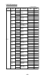

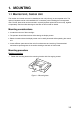
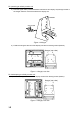
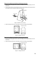
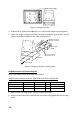
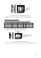

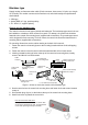
Table Of Contents
- SAFETY INSTRUCTIONS
- SYSTEM CONFIGURATION
- EQUIPMENT LISTS
- 1. MOUNTING
- 2. WIRING
- 3. INITIAL SETTINGS
- 3.1 Language Setting
- 3.2 Display Type
- 3.3 Transducer Data (FCV-1200L only)
- 3.4 Adjustment for Transceiver Unit, Video Sounder, Telesounder, Picture Recorder
- 3.5 Water Temperature Sensor Setting
- 3.6 Net Sonde Setting
- 3.7 Nav Data, Heading Sensor Setting
- 3.8 Stabilization (heaving compensation)
- 3.9 Propagation Velocity
- 3.10 Demonstration Mode
- 3.11 Restoring Default Settings
- 3.12 DIP Switch Setting
- APPENDIX 1 TRANSDUCER 50BL-12/50BL-24H
- APPENDIX 2 NEW BLT TRANSDUCERS
- APPENDIX 3 TRANSDUCER 82B-35R
- PACKING LISTS
- OUTLINE DRAWING
- INTERCONNECTION DIAGRAMS
1-4
1
2
3
4
1
2
3
4
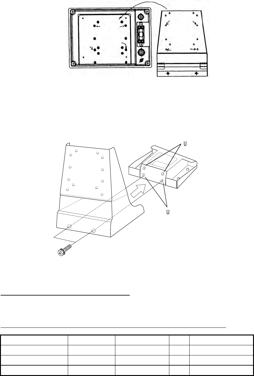
Hanger (rear view)
Figure 1-7 Hanger, rear view
3. Coat threads of upset screws (M6X16, 2 pcs.) used to fasten hanger to mounting base.
4. Fasten the hanger (or display unit) to the mounting base with two upset screws. (Use the
upper holes to tilt the display unit 20°; lower holes to tilt it 9°.)
Upset Screw
HANGER
MOUNTING
BASE
se these holes to
tilt monitor unit 20˚.
se these holes to
tilt monitor unit 9˚.
Figure 1-8 Fastening hanger to mounting base
Unibody monitor unit flush mount kit
Refer to the outline drawing at the back of this manual.
Unibody monitor unit flush mount kit: Type OP06-16, Code no. 006-556-300
Name Type Code No. Qty Remarks
Mounting Fixture 06-021-1311 100-279-610 1
Self-tapping Screw 5×20 000-162-609-10 6
Hex-head Screw M4×12 000-162-939-10 4
1. Make cutout in mounting location referring to page D-2A/D-2B.
2. Using four hex-head screws, fasten control and monitor units together with the mounting
fixture.