
Installation Instructions

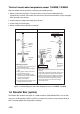
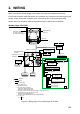
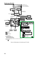
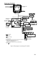
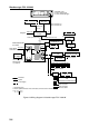
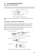
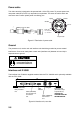
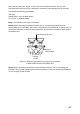
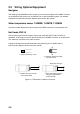
Table Of Contents
- SAFETY INSTRUCTIONS
- SYSTEM CONFIGURATION
- EQUIPMENT LISTS
- 1. MOUNTING
- 2. WIRING
- 3. INITIAL SETTINGS
- 3.1 Language Setting
- 3.2 Display Type
- 3.3 Transducer Data (FCV-1200L only)
- 3.4 Adjustment for Transceiver Unit, Video Sounder, Telesounder, Picture Recorder
- 3.5 Water Temperature Sensor Setting
- 3.6 Net Sonde Setting
- 3.7 Nav Data, Heading Sensor Setting
- 3.8 Stabilization (heaving compensation)
- 3.9 Propagation Velocity
- 3.10 Demonstration Mode
- 3.11 Restoring Default Settings
- 3.12 DIP Switch Setting
- APPENDIX 1 TRANSDUCER 50BL-12/50BL-24H
- APPENDIX 2 NEW BLT TRANSDUCERS
- APPENDIX 3 TRANSDUCER 82B-35R
- PACKING LISTS
- OUTLINE DRAWING
- INTERCONNECTION DIAGRAMS
2-6
Power cable
This video sounder is designed to be powered with 12-24 VDC power. To prevent power loss,
use power cable DPYCYS-2.0 (or equivalent) or equivalent. The armor should lie within the
connector case. Confirm polarity when connecting pins.
#1 pin (+)
#2 pin (-)
#3 pin
Lay armor in cable
S = 3.5 mm
φ = 2.4 mm
2
Armor
Vinyl Sheath
Core
Sheath
Taping
Shield
Figure 2-7 Fabrication of power cable
Ground
The processor unit, monitor unit and interface unit should be grounded to prevent mutual
interference. Connect an earth plate or earth wire (interface unit) between unit and ship’s
superstructure to ground.
Ground the equipment to
prevent electrical shock
and mutual interference.
CAUTION
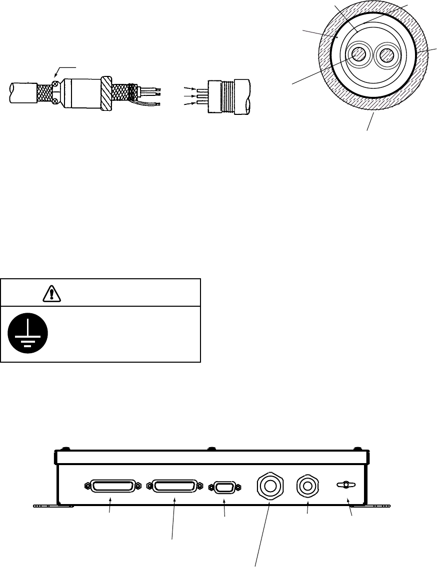
Interface unit IF-8000
The Interface Unit IF-8000 is supplied standard with the FCV-1200LM and is optionally available
with the FCV-1200L.
Earth terminal
(Ground to ship's
superstructure.)
GROUND TO
PREVENT MUTUAL
INTERFERENCE.
Navigator
Cable (06S4079)
from control
unit
VGA
Monitor
Cable (06S4078)
from monitor unit
or interface
unit
Cable (06S4078)
from processor
unit
DATA/VIDEO IN DATA/VIDEO OUT RGB OUT
CONT
NMEA
Figure 2-8 Interface unit, rear view