
Installation Instructions
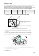
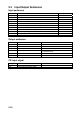
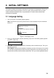
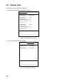
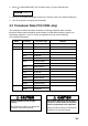
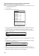
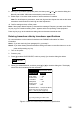
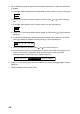

Table Of Contents
- SAFETY INSTRUCTIONS
- SYSTEM CONFIGURATION
- EQUIPMENT LISTS
- 1. MOUNTING
- 2. WIRING
- 3. INITIAL SETTINGS
- 3.1 Language Setting
- 3.2 Display Type
- 3.3 Transducer Data (FCV-1200L only)
- 3.4 Adjustment for Transceiver Unit, Video Sounder, Telesounder, Picture Recorder
- 3.5 Water Temperature Sensor Setting
- 3.6 Net Sonde Setting
- 3.7 Nav Data, Heading Sensor Setting
- 3.8 Stabilization (heaving compensation)
- 3.9 Propagation Velocity
- 3.10 Demonstration Mode
- 3.11 Restoring Default Settings
- 3.12 DIP Switch Setting
- APPENDIX 1 TRANSDUCER 50BL-12/50BL-24H
- APPENDIX 2 NEW BLT TRANSDUCERS
- APPENDIX 3 TRANSDUCER 82B-35R
- PACKING LISTS
- OUTLINE DRAWING
- INTERCONNECTION DIAGRAMS

2-9
EXIF board assy.
The EXIF board assy. (type OP02-81, code no. 000-012-463), installed inside the processor unit
CV-1203, is necessary when connecting a telesounder (on sister ship and master ship),
transceiver or other video sounder to the FCV-1200L. Below are the contents of the EXIF board
assy. kit. For connection cable use type S-02-6-10 (24P, 10 m, Code No. 002-962-030).
Name Type Code No. Qty Remarks
EXIF Assy. OP02-81 001-413-440 1
Pan Head Screw M4×10 000-163-191-10 3
SRCN Connector SRCN6A25-24P 000-160-740-10 2
1. Remove the cover of the processor unit by unfastening 13 screws (M4X8).
Unfasten 13 screws to remove cover.
Left, right, top: 6 (2 screws each side)
Heat sink: 7 screws
Unfasten two screws to remove dummy plate.
Dummy plate
Figure 2-12 Processor unit CV-1203, rear view
2. Unfasten two screws to remove the dummy plate. (The screws and plate may be
discarded.)
3. Unfasten screw marked with % in the figure below. (The screw may be discarded.)
4. Fasten the EXIF board assy. to the chassis with three screws (M4×10, supplied).
J7
J1
*- Fasten screw here.
EXIF Board
Assy.
MAIN
Board
*Screw
(M4x10)
Screw
(M4
x10)
POWER
SECTION
Figure 2-13 Processor unit CV-1203, left side view
5. Connect the EXIF Assy. between J1 on the pcb 02P6278 and J7 on the MAIN board. For
log-type video sounder, see page 3-23.
6. Close the cover.