
Operator's Manual


BOOSTER BOX BT-5 OPERATOR’S MANUAL
The Booster Box BT-5 boosts the output power of the FCV-1200L from 3 kW to 5 kW.
WARNING
ELECTRICAL SHOCK HAZARD
Do not open the equipment
unless totally familiar with
electrical circuits and
service manual.
Only qualified personnel
should work inside the
equipment.
WARNING
Turn off associated echo
sounder before beginning
the installation.
Electrical shock may result
if it is not turned off.
Standard supply
BT-5 is available in two types: single frequency and dual frequency. Refer to the Packing
List supplied with this product for details.
Available transducers
5 kW: 28F-38M, 50F-38, 10 kW: 28F-72, 50F-70
Refer to the transducer installation drawings for the transducer, thru-hull pipe and tank.
Note: 10 kW transducer can not output the maximum 10 kW power. Maximum output is
about 5 kW.
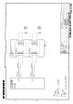
Mounting and connection
Compass safe distance: Standard, 0.9 m, Steering, 0.5 m
Choose 5 kW transducer in the initial settings of the echo sounder. For the 10 kW
transducers, set 28F-72 as “28F-38M” and 50F-70 as “50F-38.”
Low frequency side
High frequency side
4-φ6
HOT
GND
COLD
HOT
GND
COLD
COLD
GND
HOT
COLD
GND
HOT
290
240
Note: Tighten glands securely by hand.
Black
Red
Black
Red
NCS-2RNCTSB 3 m
NCS-2RNCTSB 3 m
Attach frequency labels here.
Attach frequency
labels here.
Black
Red
Ye l
Black
Red
Ye l
Tapping screw
Shield
Shield
*1= Do not connect drain wires to GND on terminals.
Use the screws provided on the chassis.
Note: For single frequency type, connect 28 kHz to
"low frequency"; 50 kHz to "high frequency."
TB1
TB1
TB2
TB2
TRANSDUCER
Connect vinyl wire
for grounding.
*1
*1
PUB. No. OMC-20280-A
BT-5
(
TENI, 0208
)