OPERATOR'S MANUAL NAVIGATIONAL ECHO SOUNDER Model FE-800 www.furuno.
IMPORTANT NOTICES General • This manual has been authored with simplified grammar, to meet the needs of international users. • The operator of this equipment must read and follow the descriptions in this manual. Wrong operation or maintenance can cancel the warranty or cause injury. • Do not copy any part of this manual without written permission from FURUNO. • If this manual is lost or worn, contact your dealer about replacement.
SAFETY INSTRUCTIONS The operator must read the safety instructions before attempting to operate the equipment. WARNING Indicates a potentially hazardous situation which, if not avoided, could result in death or serious injury. CAUTION Indicates a potentially hazardous situation which, if not avoided, could result in minor or moderate injury. Warning, Caution Prohibitive Action WARNING Mandatory Action WARNING Do not open the equipment. Do not disassemble or modify the equipment.
SAFETY INSTRUCTIONS CAUTION CAUTIO CAUTION CAUTIO Handle the LCD carefully. Observe the following compass safe distances to prevent magentic compass deviation: The LCD is made of glass, which can cause injury if broken. Standard Steering Compass Compass Do not transmit with the transducer out of water. Damage to the transducer can result. Properly adjust the gain. Too little gain gives no picture. Too much gain shows excessive noise on the picture.
TABLE OF CONTENTS FOREWORD ........................................ v SYSTEM CONFIGURATION .............. vi 1. 2.5 How to Set Bottom Link RNG ...21 2.6 How to Set the Speed of Sound........................................21 2.7 Alert Menu.................................22 2.7.1 Active alert list ...................22 2.7.2 How to display the alert log......................................23 2.7.3 Bottom lost.........................24 2.7.4 GPS lost ............................24 2.
FOREWORD A Word to FE-800 Owners Thank you for purchasing this navigational echo sounder. We are confident you will discover why FURUNO has become synonymous with quality and reliability. Since 1948, FURUNO Electric Company has enjoyed an enviable reputation for innovative and dependable marine electronics equipment. This dedication to excellence is furthered by our extensive global network of agents and dealers.
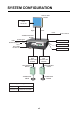
SYSTEM CONFIGURATION DISPLAY UNIT FE-8010 Printer PP-505-FE Power Signal Power RD-20 or RD-50 TRANSCEIVER UNIT FE-8020 BAM Contact signal Network Equipment or PC Ship’s MAIN 100-230 VAC RD-20 or RD-50 LAN Navigator BAM or IF-2503 JUNCTION BOX JIS F8821-1MO O-20A3P JUNCTION BOX JIS F8821-1MO O-20A3P MATCHING BOX MB-502 MATCHING BOX MB-504 TRANSDUCER 50B-6B TRANSDUCER 200B-8B Equipment category Display unit Protected from the weather Transceiver unit Protected from the weather vi
1. OPERATION 1.1 Controls All operations of the FE-800 are carried out with the controls on the front panel of the display unit. Some functions require a long key press, while others require a short key press. Removing the cover While pressing the center with your thumbs as illustrated, pull the cover towards you to remove it. DRAUGHT MENU ESC DRAUGHT Display the Main Menu.
1. OPERATION 1.2 How to Turn the Power On/Off Note 1: Make sure the unit is connected correctly to each transceiver. Note 2: After turning the unit off, wait at least 5 seconds before you turn the power on again. Press the unit off. button to turn the unit on. With the power on, press the button again to turn the On startup, the unit displays a splash screen for approximately ten seconds, then begins a self-test.
1. OPERATION 1.3 Panel and Key Brilliance Both panel and key brilliance can be adjusted from the main screen using the following procedure: 1. Press S or T on the BRILL pad to open the Brilliance pop-up window. 2. Press S or T to adjust panel brilliance. 3. Press W or X to adjust key brilliance. 4. Press the MENU/ESC key to close the pop-up window. Brilliance settings for Day or Night mode are stored separately. When changing modes, the last-used setting is restored. 1.3.
1. OPERATION 1.4 Display Modes and Screen Indications The FE-800 has 3 main display modes: NAV, HISTORY, OS DATA. The display modes are set in a cycle pattern, and each press of the DISP key changes the selected mode, in the sequence shown below. NAV HISTORY OS DATA Note 1: OS DATA mode requires external EPFS data (EG:GPS). If [Time Adjust] in the [Service] menu is set to [Internal] when initial settings are made, the OS DATA screen is unavailable.
1. OPERATION 1.4.1 NAV Mode This is the default mode for the FE-800. The screen shows depth and echo from FORE and AFT positions. The default display order of the echo readings is AFT - FORE. DRAUGHT MENU ESC DRAUGHT Display the Main Menu.
1. OPERATION 1.4.2 HISTORY Mode This mode provides a mix of Contour and Strata echo readings taken. The amount of data stored in the HISTORY log depends on the interval setting. The table below shows the differences in amount of data that can be stored. Interval setting 2 min 1 min 5 sec Amount of data stored 24 hours 12 hours 1 hour Previous echo readings can be accessed by using W or X to move the cursor. 1 2 3 DRAUGHT Number 1 2 3 DRAUGHT Description FORE/AFT depth history.
1. OPERATION 1.4.3 OS DATA Mode This mode shows Own Ship Data (OS DATA), and is only available if the [Time Adjust] setting in the [Service Menu] is set to [External]. To change the [Time Adjust] settings in the [Service Menu], consult a FURUNO technician. 1 2 3 DRAUGHT DRAUGHT 4 The OS DATA mode requires a connected EPFS device, such as GPS. If there is no device connected, or connection is interrupted, the OS DATA is displayed as shown in the above left figure.
1. OPERATION 1.5 Menu Overview 1. Press the MENU/ESC key to open the Main menu. Selected item is highlighted. Unselectable items are grey. 2. Use the S or T key to navigate the menu. The item currently selected is highlighted. 3. To choose a menu item, press the X ENT key. Depending on which item is selected, a new menu, a setting window or a setting box is displayed. Newly opened menu Settings window Settings box 4. Use the S or T key to navigate the menu or adjust settings as required. 5.
1. OPERATION 1.6 How to Select a Range The range can be set either manually or automatically. In the auto mode, the range will self-adjust to provide as clear as possible an image. The auto mode is cancelled when the range is manually adjusted. There are eight basic ranges available. Press RNG+ or RNG- to change the range. In cases where the depth goes outside the display area, adjust the range scale until the seabed appears near the center of the screen. (See section 3.1.) 1.6.
1. OPERATION 1.7.2 Automatic Operation The gain and clutter (low level noise) adjustments can be done automatically. How to turn automatic operation on or off 1. Press the MENU/ESC key to open the Main menu. 2. Select [Sounder] using S or T, then press the ENT key. 3. Select the appropriate transceiver ([FE-8020 No.1] or [FE-8020 No.2]) using S or T, then press the ENT key. 4. Select [AUTO GAIN] using S or T, then press the ENT key. This will open a pop-up window. 5.
1. OPERATION 1.8 Clutter Low level noise can cause your display to look “cluttered” with unnecessary dots. These are caused mainly by dirty water or noise. This kind of noise can be suppressed by adjusting the clutter. Note: To manually adjust the clutter, you must first turn [AUTO GAIN] off. 1. Press the MENU/ESC key to open the Main menu. 2. Select [Sounder] using S or T, then press the ENT key. 3. Select the transceiver ([FE-8020 No.1] or [FE-8020 No.
1. OPERATION 1.10 PICT Advance The picture advance menu allows you determine the speed at which the vertical scan lines run across the screen. 1. Press the MENU/ESC key to open the Main menu. 2. Select [Sounder] using S or T, then press the ENT key. 3. Select [PICT Advance] using S or T, then press the ENT key. This will open a pop-up window. 4. Select [FAST] or [SLOW] as appropriate, using S or T, then press the ENT key. [FAST] picture advance expands the echo sideways across the screen.
1. OPERATION 1.12 How to Use the Function Key The function key can store and recall a preset location in the menu. You can recall the function by pressing the FUNC key. To store a function 1. Navigate the menu to the function you wish to store. 2. Press and hold the FUNC key to store the menu function. A small asterisk “*” will appear next to the menu item when it is stored. In the example below, [Manual GAIN] is stored to the FUNC key. Menu item stored to function key. 3.
1. OPERATION 1.14 How to Choose a Transceiver If your FE-800 is connected to two transceivers, you can switch between the transceivers using the procedure below. Note: If [FE-8020 No.2] is not enabled in the [Service Menu], this menu is not selectable. To enable [FE-8020 No.2], consult a FURUNO technician. 1. Press the MENU/ESC key to open the Main menu. 2. Select [FE-8020 Select] using S or T, then press the ENT key. This will open a pop-up window. 3.
1. OPERATION 1.16 How to Set Draught Draught can be set in two locations, [FORE] and [AFT], if your vessel has transducers at both of these locations. If your vessel only has one transducer, the draught is set at the transducer location only. To set the draught for your vessel, do the following: 1. Press the MENU/ESC key to open the Main menu. 2. Select [Sounder] using S or T, the press the ENT key. 3. Select the appropriate transceiver to set ([FE-8020 No.1] or [FE-8020 No.2]), then press the ENT key.
1. OPERATION How to change the logging interval The logging interval for each entry can be adjusted in the menu by doing the following: 1. Press the MENU/ESC key to open the Main menu. 2. Select [Display] using S or T, then press the ENT key. 3. Select [Interval] using S or T then press the ENT key. The Interval settings pop-up window will open. 4. Choose the appropriate interval (5 s - 1 hour max., 1 min - 12 hours max., 2 min - 24 hours max.
1. OPERATION 1.18 How to Change the Unit of Measurement You can change the displayed unit of measurement for depth and speed using the following procedure. 1. Press the MENU/ESC key to open the Main menu. 2. Select [Display] using S or T, then press the ENT key. 3. Select [Unit] using S or T, then press the ENT key. This will open the [Unit] pop-up window. 4. Select the [Depth] or [Speed] using S or T, then press ENT to open the settings pop-up window. The available options are shown in the table below.
2. SYSTEM MENU The [System Menu] should be preset at installation. Normally, there is no need to access this menu. Note: The echo display will be cleared when the [System Menu] is opened. 2.1 How to Set the Basic Range Scale Use the table below for reference when changing the range scale settings. Depending on your configuration, some options may not be available.
2. SYSTEM MENU 2.2 How to Set Transducer Parameters 1. Press the MENU/ESC key to open the Main menu. 2. Select [System] using S or T, then press the ENT key. 3. Select [Parameters] using S or T, then press the ENT key. 4. Select [FE-8020 No. 1] or [FE-8020 No. 2] as appropriate using S or T, then press the ENT key. 5. Select the parameter you wish to set using S or T, then press the ENT key. This will open a pop-up window. The table below shows the available menu items and their available settings.
2. SYSTEM MENU 2.2.2 TVG level TVG (Time Varied Gain) compensates for propagation attenuation of the ultrasonic waves, reducing surface noise to provide a smooth display. The TVG lowers receiver sensitivity at the time of pulse emission and gradually increases it with time, thereby making objects of same reflectivity at different depths appear at the same intensity or colors on the display. The TVG working depth is down to approximately 150 m on the 200 kHz system and 350 m on the 50 kHz system.
2. SYSTEM MENU 2.4 How to Set Bottom Tail Display You can change the color of the stronger echoes on the seabed by using the [Bottom Tail Display] function. 1. Press the MENU/ESC key to open the Main menu. 2. Select [System] using S or T, then press the ENT key. 3. Select [Parameters] using S or T, then press the ENT key. 4. Select [Bottom Tail Display] using S or T, then press the ENT key. This will open a pop-up window. 5.
2. SYSTEM MENU 2.7 Alert Menu 2.7.1 Active alert list The [Active Alert] list shows the currently active alerts. 1. Press the MENU/ESC key to open the Main menu. 2. Select [System] using S or T, then press the ENT key. 3. Select [Alert] using S or T, then press the ENT key. 4. Select [Active Alert] list using S or T, then press the ENT key. 230 Depth below Keel Alarm 101 TX Volt Error1 102 RX Volt Error1 103 TCVR High Temperature1 950 BAM COM Error 5. To change pages, use W or X. 6.
2. SYSTEM MENU 2.7.2 How to display the alert log The [Alert Log] tracks all alerts. 1. Press the MENU/ESC key to open the Main menu. 2. Select [System] using S or T, then press the ENT key. 3. Select [Alert] using S or T, then press the ENT key. 4. Select [Alert Log] using S or T, then press the ENT key. Page No.
2. SYSTEM MENU 2.7.3 Bottom lost The FE-800 can output an alert when the seabed echo is lost. To adjust the alert settings, do the following: 1. Press the MENU/ESC key to open the Main menu. 2. Select [System] using S or T, then press the ENT key. 3. Select [Alert] using S or T, then press the ENT key. 4. Select [Bottom Lost] using S or T, then press the ENT key. 5. Select [ON] to output an alert, select [OFF] to stop alert output. 6. Press the DISP key to close the open menus. 2.7.
2. SYSTEM MENU 2.8 Alarms, Warnings and Cautions When an error occurs, the system will attempt to notify the user with an audible alarm and a popup message window, similar to the one shown below. 230 Depth below Keel Alarm ALARM ACK Acknowledge Press the ALARM ACK key to acknowledge the alert and stop the audible alarm. There are three priority-based levels to which the alert notification can be assigned.
2. SYSTEM MENU 2.8.1 Icon Alert icons and their meanings Description Active-unacknowledged notification, icon is flashing. The cause of the notification is still present. Flashing: One second interval, 0.5 second ON time. Buzzer: Three short audible beeps, followed by seven seconds silence, then repeats. Active-silenced notification, icon is flashing. The buzzer has been silenced, the cause of the notification is still present. Flashing: One second interval, 0.5 second ON time. Buzzer: Silent.
2. SYSTEM MENU 2.9 How to Set or Adjust the Time The unit can display the time from an external EPFS device (such as GPS), or the unit’s internal clock. The time source is selected during the initial installation and requires a FURUNO technician to adjust the setting. The source which has not been selected at installation will be displayed as a grey, unselectable menu item in the [Ship’s Time] menu. The example below shows [External] as the selected source, with [Internal] as unselectable (grey).
2. SYSTEM MENU 2.9.2 Internal time The internal clock can be set to show the day, month, year, hour, minute and second. By default, this is set to "00:00:00 1/Jan/2014". You can adjust the time as follows. 1. Press the MENU/ESC key to open the Main menu. 2. Select [System] using S or T, then press the ENT key. 3. Select [Ships’s Time] using S or T, then press the ENT key. 4. Select [Internal] using S or T, then press the ENT key. This will open a pop-up window. 5.
2. SYSTEM MENU 2.11 System Information The system information display shows information about your FE-800 unit and the transceiver(s) connected to it. The figure below is an example of the information screen. 1. Press the MENU/ESC key to open the Main menu. 2. Select [System] using S or T, then press the ENT key. 3. Select [Information] using S or T, then press the ENT key. A confirmation pop-up window will appear. 4. Select [FE-8010], [FE-8010 No.1] or [FE-8020 No.
3. MAINTENANCE AND TROUBLESHOOTING WARNING NOTICE Do not apply paint, anti-corrosive sealant or contact spray to coating or plastic parts of the equipment. Do not open the cover. There are no user-serviceable parts inside. Those items contain organic solvents that can damage coating and plastic parts, especially plastic connectors. Refer any repair work to a qualified technician. 3.1 Checklist Regular maintenance is essential for good performance.
3. MAINTENANCE AND TROUBLESHOOTING 3.4 Replacing the Fuse/Battery If a fuse blows, find the cause before replacing it. Use only designated fuses. Using the wrong fuse will damage the unit and void the warranty. Consult your dealer for replacement of the fuse. A battery installed on a circuit board inside the transceiver unit preserves data when the power is turned off. The life of the battery is about ten years. When the battery voltage is low, a warning message "Displayed time may be incorrect.
APPENDIX 1 MENU TREE MAIN MENU ├ 1 Day/Night ├ 2 Depth Alarm ├ 3 Output Depth ├ 4 FE-8020 Select ├ 5 Sounder ├ 6 Display └ 7 System All default settings are in bold italic 1 Day/Night (Day /Night) 2 Depth Alarm (0 to 2400m) Default=20m 3 Output Depth (AFT/FORE) 4 FE-8020 Select (No. 1 , No. 2) 5 Sounder ├ DEPTH (BELOW) (Transducer, Keel , Surface) │ ├ FE-8020 No. 1 │ ├ Draught (0.0m to 30.
APPENDIX 1 MENU TREE 7 System ├ Range Default=5m │ ├ Basic Range1 (2 to 18) Default=10m │ ├ Basic Range2 ((BR1+1) to (BR3-1)) Default=20m Basic Range3 (20) │ ├ Default=40m │ ├ Basic Range4 (21 to (BR5-1)) Default=100m Basic Range5 ((BR4+1) to 199) │ ├ Default=200m Basic Range6 (200) │ ├ Default=400m │ ├ Basic Range7 (201 to (BR8-1)) Default=800m │ └ Basic Range8 ((BR7+1) to 2400) │ ├ System Parameters │ ├ No.
APPENDIX 2 PARTS LOCATIONS Transceiver unit FE8020 PWR board 12P1002 TRX board 12P1001 Remove cover to show FIL board 12P1003 Remove MAIN board to show TRX board FIL board MAIN board 12P1000 Display unit FE-8010 Remove DISP board to show lower boards DISP board 12P1004 Remove bracket to show MCN board 02P6345 LCD board NL6448BC226-22F PNL board 26P0007 AP-3
APPENDIX 3 LIST OF TERMS AND ABBREVIATIONS Term ADD ACK ADJ AFT ALARM ALERT Apr Aug AUTO BAM BRILL COG COM CONFIG DATA DBS DE Dec DEMO DEST DISP DRAUGHT Meaning Address Acknowledge Adjust Aft Alarm Alert April August Automatic Bridge Alert Management Brilliance Course Over the Ground Communication Configuration Data Depth Below Surface Decca Navigator December Demonstration Destination Display Draught Term IR I/F I/O IP Jan Jul Jun KEEL kn km/h KP LA LC LCD LOG LOGBOOK m Mar May MENU MPH NMEA ENT EPFS ES
APPENDIX 3 LIST OF TERMS AND ABBREVIATIONS Term TRANSDUCER, XDR TVG TX UTC Meaning Transducer Time Varied Gain Transmit Universal Time, Coordinated AP-5
FURUNO FE-800 SPECIFICATIONS OF NAVIGATIONAL ECHO SOUNDER FE-800 1 1.1 1.2 1.3 1.4 1.5 TRANSCEIVER UNIT Transmit frequency Output power Measuring range Accuracy Basic display range Unit 1.6 Meter Feet Roll/pitch tolerance 1.7 Data recording period 1.8 Display mode 50 kHz, 200 kHz or alternating transmit among these frequencies 1 kWrms 2 to 200 m on 50 kHz, 1 to 200 m on 200 kHz 0.5 m at 20 m range, 5 m at 200 m range, or 2.
FURUNO Output FE-800 ALC, ALF, ALR, ARC, DBK*1, DBS*1, DBT*2, DPT, HBT *1: Not SOLAS compliant. *2: Available when the transducer face is same level as keel. 3.3 Output proprietary sentence PFEC msi (mandatory, for multiple transducer installation) 3.4 Alarm output Dry contact, Normal open/close (24 VDC/ 2 A) 4 4.1 4.2 4.3 POWER SUPPLY Transceiver unit Display unit Printer (option) 5 5.1 5.2 5.3 5.
INDEX A Alert menu...................................................22 active alert list ...........................................22 alert log .....................................................23 bottom lost.................................................24 GPS lost ....................................................24 Automatic operation ....................................10 M Maintenance and troubleshooting ...............30 alarm list....................................................
The paper used in this manual is elemental chlorine free. ・FURUNO Authorized Distributor/Dealer 9-52 Ashihara-cho, Nishinomiya, 662-8580, JAPAN All rights reserved. Printed in Japan A : MAY 2014 A3 : JUL . 29, 2014 Pub. No.