MARINE RADAR FR-8062, FR-8122, FR-8252
The paper used in this manual is elemental chlorine free. FURUNO Authorized Distributor/Dealer 9-52 Ashihara-cho, Nishinomiya 662-8580, JAPAN Telephone : 0798-65-2111 Fax 0798-65-4200 : All rights reserved. Printed in Japan FIRST EDITION : SEP. 2005 E1 Pub. No. OME-35390 ( DAMI ) FR-8062/8122/8252 : OCT.
SAFETY INSTRUCTIONS IMPORTANT NOTICES • This manual is intended for use by native speakers of English. • No part of this manual may be copied or reproduced without written permission. • If this manual is lost or worn, contact your dealer about replacement. • The contents of this manual and equipment specifications are subject to change without notice. • The example screens (or illustrations) shown in this manual may not match the screens you see on your display.
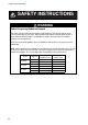
SAFETY INSTRUCTIONS SAFETY INSTRUCTIONS WARNING Radio Frequency Radiation Hazard The radar antenna emits electromagnetic radio frequency (RF) energy which can be harmful, particularly to your eyes. Never look directly into the antenna aperture from a close distance while the radar is in operation or expose yourself to the transmitting antenna at a close distance. Distances at which RF radiation levels of 100 W/m2 and 10 W/m2 exist are given in the table below.
SAFETY INSTRUCTIONS WARNING ELECTRICAL SHOCK HAZARD WARNING Use the proper fuse. Do not open the equipment. Only qualified personnel should work inside the equipment. Fuse rating is shown on the equipment. Use of a wrong fuse can result in damage to the equipment. Keep heater away from equipment. Turn off the radar power switch before servicing the antenna unit. Post a warning sign near the switch indicating it should not be turned on while the antenna unit is being serviced.
SAFETY INSTRUCTIONS WARNING No one navigational aid should be relied upon for the safety of vessel and crew. The navigator has the responsibility to check all aids available to confirm position. Electronic aids are not a substitute for basic navigational principles and common sense. • The ARP automatically tracks automatically or manually acquired radar targets and calculates their courses and speeds, indicating them by vectors.
TABLE OF CONTENTS TABLE OF CONTENTS FOREWORD ............................................................................................... ix SYSTEM CONFIGURATION ...................................................................... xi 1. OPERATIONAL OVERVIEW..............................................................1-1 1.1 1.2 1.3 1.4 1.5 1.6 1.7 1.8 1.9 1.10 1.11 1.12 1.13 1.14 1.15 1.16 1.17 1.18 1.19 1.20 1.21 Controls .....................................................................
TABLE OF CONTENTS 1.22 Zoom ....................................................................................................................... 1-27 1.22.1 How to zoom ............................................................................................. 1-27 1.22.2 Zoom mode ............................................................................................... 1-28 1.23 Echo Stretch.........................................................................................................
TABLE OF CONTENTS 2. RADAR OBSERVATION ....................................................................2-1 2.1 2.2 2.3 2.4 General......................................................................................................................2-1 2.1.1 Minimum and maximum ranges ..................................................................2-1 2.1.2 Radar resolution ..........................................................................................2-2 2.1.3 Bearing accuracy ........
TABLE OF CONTENTS 5. GPS OPERATION .............................................................................. 5-1 5.1 5.2 5.3 5.4 5.5 5.6 5.7 Navigator Type.......................................................................................................... 5-1 Datum........................................................................................................................ 5-2 WAAS Setup ..................................................................................................
FOREWORD A Word to the Owner of the FR-8xx2 Marine Radar FURUNO Electric Company thanks you for purchasing the FR-8xx2 series Color LCD Marine Radar. We are confident you will discover why the FURUNO name has become synonymous with quality and reliability. For over 50 years FURUNO Electric Company has enjoyed an enviable reputation for quality and reliability throughout the world. This dedication to excellence is furthered by our extensive global network of agents and dealers.
FOREWORD Radar Specifications and Function Availability This radar series is available in three specification types (river, sea and IEC), and function availability depends on specification type. The table below shows specification type and function availability. River: For river-going vessels Sea: For sea-going vessels IEC: IEC compliant radar Specification and function availability Item Specification Description River Sea Ref.
SYSTEM CONFIGURATION FR-8252 ANTENNA UNIT RSB-0073-087-XN12A/XN13A POWER SUPPLY UNIT PSU-008 Auto Plotter ARP-11 DISPLAY UNIT RDP-150 (built into display unit) Gyrocompass RGB Gyro Converter AD-100 100/110/ 115/220/ 230 VAC, 1φ Rectifier RU-3423 Heading Sensor PG-1000 12-24 VDC NMEA Device Remote Display NMEA Device Commercial Monitor (SVGA or better) External Buzzer OP03-136 OR Category of units Antenna unit: Exposed to weather All other units: Protected from weather Remote Controller RCU-01
SYSTEM CONFIGURATION FR-8122, FR-8062 ANTENNA UNIT RSB-0073-085-XN12A/XN13A: FR-8062 RSB-0073-086-XN12A/XN13A: FR-8122 Auto Plotter ARP-11 DISPLAY UNIT RDP-150 (built into display unit) Gyrocompass RGB Gyro Converter AD-100 100/110/ 115/220/ 230 VAC, 1φ Rectifier RU-3423 Heading Sensor PG-1000 12-24 VDC NMEA Device Remote Display NMEA Device Commercial Monitor (SVGA or better) External Buzzer OP03-136 OR Remote Controller RCU-019 Category of units Antenna unit: Exposed to weather All other un
1. OPERATIONAL OVERVIEW 1.1 Controls 1.1.1 Display unit This radar is operated with the controls of the display unit (and the remote controller), which includes 18 keys that are labeled with their functions, three knob controls and a trackball. When you correctly execute an operation, the unit generates a beep. Invalid operation causes the unit to emit several beeps. No.
1. OPERATIONAL OVERVIEW 1.1.2 Remote controller The optional remote controller provides armchair control over transmit, standby, range and display offcentering (30% in stern direction). Offcenters display. OFF CENTER STBY TX RANGE Remote controller 1-2 Toggles STBY/TX. Chooses range.
1. OPERATIONAL OVERVIEW 1.2 Turning the Radar On/Off, Transmitting Press the POWER/BRILL key at the top of the control panel to turn the radar on, and the lamp to its left lights. To turn the radar off, press and hold down the key until the screen turns black. At power-up, the start-up screen appears, showing the model name, program number and the results of the ROM and RAM check, OK or NG (No Good). If an NG appears, try pressing any key other than the power key to proceed.
1. OPERATIONAL OVERVIEW 1.3 Display Indications Presentation mode Auto adjustment of rain and sea clutters Range ring interval Offcenter (M: Manual, A: Auto) Range Pulse length Custom setting name Echo stretch (ES), Echo averaging (EAV) 0.25 0.75 NM SP OFFCENTER(M) H UP HARBOR A/C AUTO Heading 359.
1. OPERATIONAL OVERVIEW 1.4 Adjusting Display Brilliance, Panel Dimmer The display brilliance and panel dimmer may be adjusted as follows: 1. Press the POWER/BRILL key momentarily to show the Brill/Panel dialog box. Brill/Panel W Min Max X Brill (1 - 15) 15 Panel (1 - 15) 15 [ENTER]: Select [CANCEL/HL OFF]: Close Brill/Panel dialog box 2. Press the ENTER key to choose Brill or Panel, whichever you wish to adjust. 3. Roll the trackball rightward or leftward to adjust.
1. OPERATIONAL OVERVIEW Menu description Brill/Color: Choose colors; adjust range ring brilliance. DIsplay: Control display functions. Echo: Adjust radar echo. Target Trails: Process target trails. Mark: Process markers such as VRM and EBL. Custom 1-Custom 3: One-touch set up for given navigation situation. Tuning: Adjust radar tuning. GPS Buoy: Set up GPS buoy display. Target: Set up ARP and AIS targets. ARP: Set up ARP display. AIS: Set up AIS display.
1. OPERATIONAL OVERVIEW 1.6 Tuning The radar receiver can be tuned automatically or manually, and the default tuning method is automatic. If you require manual tuning, do the following: 1. Use the RANGE key to choose the 48-mile range. 2. Press the MENU key to display the main menu. 3. Use the trackball to choose Tuning and press the ENTER key.
1. OPERATIONAL OVERVIEW 1.7 Presentation Modes This radar has the following presentation modes: Relative Motion (RM) Head-up: Unstabilized display. Heading is at the top of the screen. Course-up: Compass-stabilized relative to ship's orientation. The bearing scale rotates to place ship’s heading (course set) at the screen top at the moment the course-up mode is selected. North-up: Compass-stabilized with reference to north. Bearing scale is fixed.
1. OPERATIONAL OVERVIEW Course-up mode North Marker Heading Line The course-up mode is an azimuth stabilized display in which a line connecting the center with the top of the display indicates own ship's intended course (namely, own ship's previous heading just before this mode has been selected). Target pips are painted at their measured distances and in their directions relative to the intended course, which is maintained at the 0degree position.
1. OPERATIONAL OVERVIEW Automatic resetting of own ship marker in true motion mode North marker Heading line (a) True motion is selected 1.8 (b) Own ship has reached a point 75% of display radius (c) Own ship is automatically reset to 75% of radius Choosing a Range Scale The selected range scale, range ring interval and pulse length are shown at the upper left corner on the screen. When a target of interest comes closer, reduce the range scale so that it appears in 50-90% of the display radius.
1. OPERATIONAL OVERVIEW 1.9 Choosing a Pulse Length The pulse length in use appears at the top left position on the screen. Appropriate pulse lengths are preset to individual range scales and custom setups. If you are not satisfied with the pulse length setting on the 1.5 nm or 3 nm range, you may change it as below. (Pulse length cannot be changed on any other ranges.) Use a longer pulse when your objective is long range detection, a shorter pulse when resolution is important. 1.
1. OPERATIONAL OVERVIEW 1.10 Adjusting the Gain (sensitivity) The gain functions to adjust the receiver sensitivity for the best reception of signals of widely varying amplitudes. 1.10.1 Choosing gain adjustment method Gain may be adjusted automatically or manually. Push the GAIN control to choose automatic or manual adjustment alternately. The adjustment method currently chosen is show at the top right corner of the screen. In the example below the gain adjustment method is “AUTO”.
1. OPERATIONAL OVERVIEW 1.11 Suppressing Sea Clutter Echoes from waves cover the central part of the display with random signals known as sea clutter. The higher the waves, and the higher the antenna above the water, the further the clutter will extend. When sea clutter masks the picture, use the A/C SEA control to suppress the clutter, either manually or automatically. 1.11.1 Choosing sea clutter adjustment method Push the A/C SEA control to choose automatic or manual adjustment alternately.
1. OPERATIONAL OVERVIEW 1.11.3 Manual sea clutter adjustment 1. Push the A/C SEA control to show “SEA MAN” as the A/C SEA adjustment method. 2. Rotate the A/C SEA control to suppress sea clutter. The proper setting of the A/C SEA control is such that the clutter is broken up into small dots, and small targets become distinguishable. If the setting is set too low, targets will be hidden in the clutter, while if the setting is too high, both sea clutter and targets will disappear from the display.
1. OPERATIONAL OVERVIEW 1.12.2 Setting automatic rain clutter suppression level 1. Press the MENU key to open the menu. 2. Choose the Echo menu and press the ENTER key. 3. Choose Auto Rain and press the ENTER key. Rough Moderate Calm 4. Choose the option which best matches current sea condition and press the ENTER key. 5. Press the MENU key to close the menu. Rain clutter is automatically adjusted according to the level selected. 1.12.3 Manual rain clutter adjustment 1.
1. OPERATIONAL OVERVIEW 1.13 Automatic Suppression of Sea and Rain Clutters If neither sea clutter or rain clutter are sufficiently suppressed in spite of adjustment of respective controls, turn on the automatic anti clutter feature to suppress them. A/C AUTO appears at the top left corner when this feature is turned on. 1. Press the MENU key to open the menu. 2. Choose the Echo menu and press the ENTER key. 3. Choose Auto Anti Clutter and press the ENTER key. Off On 4.
1. OPERATIONAL OVERVIEW 1.14 Cursor The cursor functions to find the range and bearing (default function) to a target or the latitude and longitude position of a target. Roll the trackball to position the cursor and read the cursor data at the screen bottom. 3 0.5 NM + Cursor + 110.1°R 2.525 NM Cursor data (latitutde and longitude or range and bearing) Cursor data Cursor data Cursor data can be shown as latitude and longitude or range and bearing from own ship to the cursor.
1. OPERATIONAL OVERVIEW 1.15 Interference Rejector Mutual radar interference may occur in the vicinity of another shipborne radar operating in the same frequency band (9 GHz). It is seen on the screen as a number of bright spikes either in irregular patterns or in the form of usually curved spoke-like dotted lines extending from the center to the edge of the picture. Activating the interference rejector circuit can reduce this type of interference. Interference 1. Press the MENU key to open the menu. 2.
1. OPERATIONAL OVERVIEW 1.16 Measuring the Range to a Target The range to a target may be measured three ways: with the fixed range rings, with the cursor (if set to measure range and bearing), and with the VRM. Use the fixed range rings to obtain a rough estimate of the range to a target. They are the concentric solid circles about own ship, or the sweep origin.
1. OPERATIONAL OVERVIEW 1.16.2 Choosing VRM unit The unit of measurement used by the VRM can be selected to nautical miles, kilometers, statute miles or kiloyard. Note that the cursor range unit is also changed when the VRM unit is changed. 1. Press the MENU key to open the menu. 2. Choose the Mark menu and press the ENTER key. 3. Choose VRM Unit and press the ENTER key. nm km sm kyd nm&yd 4. Choose desired unit and press the ENTER key. 5. Press the MENU key to close the menu.
1. OPERATIONAL OVERVIEW 1.17 Turning Range Rings On/Off, Adjusting Range Ring Brilliance 1. Press the MENU key to open the menu. 2. Choose the Brill/Color menu and press the ENTER key. Menu Brill/Color Display Echo Target Trails Mark Custom 1 Custom 2 Custom 3 Tuning GPS Buoy Target ARP AIS GPS System Brill/Color Range Rings Brill Echo Color Display Color Background Color :High :Yellow :Night :Black/Green [ENTER]: Enter [CANCEL/HL OFF]: Back [MENU]: Exit 3.
1. OPERATIONAL OVERVIEW 1.18 Measuring the Bearing to a Target Use the Electronic Bearing Lines (EBLs) to take bearings of targets. There are two EBLs, No. 1 and No. 2. Each EBL is a straight dashed line extending out from the own ship position up to the circumference of the radar picture. The fine dashed line is the No. 1 EBL and the coarse dashed one is the No. 2 EBL. 1.18.1 Measuring the bearing with an EBL 1. Press the EBL key to display either of the EBLs.
1. OPERATIONAL OVERVIEW 1.18.2 EBL reference The EBL readout is affixed by "R" (relative) if it is relative to own ship's heading, "T" (true) if it is referenced to the north. You may choose relative or true in the head-up modes; in all other modes it is always TRUE. True bearing requires a heading sensor. 1. Press the MENU key to open the menu. 2. Choose the Mark menu and press the ENTER key. 3. Choose EBL Reference and press the ENTER key. Relative True 4.
1. OPERATIONAL OVERVIEW 1.20 Target Alarm The target alarm serves to alert the navigator to targets (ships, landmasses, etc.) entering a set area, with audio and visual alarms. CAUTION The alarm may be set to sound against targets entering or exiting the zone. See paragraph 1.20.3. 1.20.1 Setting a target alarm The procedure which follows shows you how to set a target alarm, using the illustration below as an example.
1. OPERATIONAL OVERVIEW 1.20.3 Choosing alarm type As noted earlier the target alarm may be set sound against targets entering or exiting the alarm. Choose desired type as below. Inward target alarm Outward target alarm In and Out alarms 1. Press the MENU key to shown the menu. 2. Choose the Mark menu and press the ENTER key. 3. Choose Target Alarm 1 Mode or Target Alarm 2 Mode as appropriate and press the ENTER key. In Out 4.
1. OPERATIONAL OVERVIEW 1.20.6 Choosing target strength which triggers target alarm You may choose the target strength level which triggers the alarm as follows: 1. Press the MENU key to open the menu. 2. Choose the Initial sub menu from the System menu and the press the ENTER key. 3. Choose Alarm Level and press the ENTER key. Low Med High 4. Choose the echo strength level which you want to trigger the target alarm. 5. Press the ENTER key. 6. Press the MENU key to close the menu. 1.
1. OPERATIONAL OVERVIEW Activating automatic off center Press the OFF CENTER key to display OFF CENTER (A) at the top of the screen. Own ship position is placed at stern position and shifts according to own ship’s speed. To cancel automatic shift press the key again. 1.21.2 Manual off center The own ship position may be shifted to the cursor position on any mode, within 75% of the effective display area. 1. Place the cursor where you want to locate sweep origin. 2.
1. OPERATIONAL OVERVIEW 2. Do one of the following depending on the zoom mode in use. Relative or true zoom mode 1. Use the trackball to place the cursor where you want to zoom and press the ENTER key. The zoom cursor is shown with solid lines and is fixed at the location chosen. Each press of the ZOOM key enables or disables the zoom cursor. The zoom cursor is shown with dashed lines when it is active and solid lines when it is inactive. 2.
1. OPERATIONAL OVERVIEW 1.23 Echo Stretch The echo stretch feature enlarges targets in the range and bearing directions to make them easier to see, and is available on any range. There are three levels of echo stretch as shown in the table below. Echo stretch settings ES Setting Stretch in range direction Stretch in bearing direction 1 Stretched +2 dots An echo is stretched to three dots in size in bearing direction if it is less than three dots in bearing direction.
1. OPERATIONAL OVERVIEW 1.24 Echo Averaging To distinguish real target echoes from sea clutter, echoes are averaged over successive picture frames. If an echo is solid and stable, it is presented in its normal intensity. Sea clutter is averaged over successive scans resulting in reduced brilliance, making it easier to discriminate real targets from sea clutter. Note •Do not use the echo average function under heavy pitching and rolling; loss of target detection can result.
1. OPERATIONAL OVERVIEW 1.25 Target Trails The trails of the radar targets may be displayed in the form of synthetic afterglow. Target trails are chosen either relative or true. True motion trails require a heading bearing signal and position data. 1.25.1 Starting, stopping trails 1. Press the TRAILS key to start trails and choose trail time. The chosen time, along with trail mode, is shown at the bottom left corner as shown in the figure below. Trail time is available among 15 s, 30 s, 1 min., 3 min.
1. OPERATIONAL OVERVIEW 1.25.2 Trail mode You may display echo trails in true or relative motion. Relative trails show relative movements between targets and own ship. True motion trails present true target movements in accordance with their over-the-ground speeds and course, and require a gyrocompass signal and own ship speed input. (a) True target trails (No smearing of stationary targets) (b) Relative target trails (Targets moving relative to own ship) To choose trail mode, do the following: 1.
1. OPERATIONAL OVERVIEW 1.25.3 Trail gradation Trails may be shown in single or multiple gradation. Multiple gradation provides gradual shading over time. This feature is available when Length on the Target Trails menu is set to Normal. 1. Press the MENU key to open the menu. 2. Choose the Target Trails menu and press the ENTER key. 3. Choose Trail Gradation and press the ENTER key. Single Multi 4. Choose Single or Multi and press the ENTER key. Single (Monotone shading) Multiple (Gradual shading) 5.
1. OPERATIONAL OVERVIEW 1.25.6 Trail copy The trail copy feature, which is turned on in the default setting, lets you continue tracing target trails when switching the range. However, if the newly selected range is less than 1/4 of the previous range, trails are erased. When this feature is turned off, trails are erased and restarted whenever the range is changed. Note that the restart trails feature (see paragraph 1.24.9) must be turned on to use trail copy.
1. OPERATIONAL OVERVIEW 1.25.9 Restarting trails When the range is changed while the trail feature is active, trails within the former range scale may stopped and restarted. The relationship between trail restart and trail copy is shown in the table below. Restart feature Trail copy feature Action Off On or Off Range switched to adjacent range scale All trails are erased when range is changed. Trails are not restarted. Return to previous range scale Previous trails are displayed and are continued.
1. OPERATIONAL OVERVIEW 5. Choose Time and press the ENTER key. 12h:00m 12h:00m (00h:30m-12h:00m) (01h:00m-24h:00m) 12 hour 24 hour 6. Roll the trackball upward or downward as appropriate to set time and press the ENTER key. 7. Press the MENU key to close the menu. 1.26 Parallel Index Lines Parallel index lines are useful for keeping a constant distance between own ship and a coastline or a partner ship when navigating. You may control the orientation and line interval.
1. OPERATIONAL OVERVIEW 1.26.3 Parallel index lines mode You may choose the index line orientation against the No. 2 EBL (dashed line) for parallel or vertical as follows: 1. Press the MENU key to open the menu. 2. Choose Mark and press the ENTER key. 3. Choose Parallel Line Mode and press the ENTER key. Parallel Vertical 4. Choose Parallel or Vertical as appropriate and press the ENTER key. Vertical Parallel 5. Press the MENU key to close the menu. 1.
1. OPERATIONAL OVERVIEW 1.27.2 Origin mark mode You may choose how the origin mark moves on the screen, from True (mark fixed against landmass) or Relative (marked fixed against own ship position). The True requires heading bearing signal and position data. 1. Press the MENU key to open the menu. 2. Choose Mark and press the ENTER key. 3. Choose Origin Mark Mode and press the ENTER key. Relative True 4. Choose Relative or True as appropriate and press the ENTER key. 5.
1. OPERATIONAL OVERVIEW 1.29.2 Description of custom setup items Description of custom setup items Menu item Available settings See para., page Custom 1, 2 or 3 Turn respective custom program on/off. Copy Copy settings from the Echo menu. Name Choose name of custom setup among harbor, long, sea, rain, buoy, and bird. Gain Rough, Moderate, Calm: Automatic gain adjustment according to sea state. Manual: Manual adjustment 1.
1. OPERATIONAL OVERVIEW 1.29.3 Setting custom setups 1. Press the MENU key to show the menu. 2. Choose Custom 1, Custom 2 or Custom 3 as appropriate and press the ENTER key.
1. OPERATIONAL OVERVIEW 1.30 Programming Function Keys (F1 and F2 keys) Many functions are provided in the menu. To avoid opening the menus to set up the radar for a particular situation, you may program a function key, F1 and F2, to provide one-touch access to a desired function. Function key operation To activate a function, simply press the appropriate function key, F1 or F2. Push the same function key again to display appropriate option and press the ENTER key.
1. OPERATIONAL OVERVIEW 1.31 Noise Rejector White noise may show itself on the screen as random "speckles" spread over the entire display. You can suppress this noise as follows: 1. Press the MENU key to show the menu. 2. Choose Echo and press the ENTER key. 3. Choose Noise Rejector and press the ENTER key. Off Low Med High 4. Choose Off, Low, Med or High as appropriate and press the ENTER key. 5. Press the MENU key to close the menu. 1.
1. OPERATIONAL OVERVIEW 1.33 Watchman The Watchman feature transmits for one minute at the elapse of the chosen time interval to help you keep regular watch of the radar picture for safety or other purposes. Tx 1 min Watchman starts ST-BY * 5,10 or 20 min. * Tx ST-BY 1 min. 5,10 or 20 min. * Beep emitted just before radar transmits. How watchman works In standby condition, the timer below the WATCH label at the upper right corner of the screen counts down the time remaining until transmission.
1. OPERATIONAL OVERVIEW 1.34 Color Schemes 1.34.1 Preset color schemes Preset color schemes are provided for optimum viewing in daytime, nighttime and twilight. Below are the default color settings for each preset color scheme. Display item, color scheme and color DIsplay item Text Range rings Echo Background Day Black Green Yellow White Night Red Red Green Black Twilight Green Green Green Blue User Green Green Yellow Black 1. Press the MENU key to show the menu. 2.
1. OPERATIONAL OVERVIEW 1.35 Navigation Data 1.35.1 Navigation data during standby Navigation data is shown in standby when STBY Mode Display in the Initial Menu is set to “Nav”. Appropriate sensors required to display data. Cross-track error Time until Tx in watchman (Displayed when watchman is active.) Heading XTE Waypoint Flashes if vessel goes outside display bearing. Own ship marker Fixed regardless of ship's movement. ←9.99nm W 359.9° NNW NW STBY NNE N SPEED COURSE 12.
1. OPERATIONAL OVERVIEW Depth and water temperature graphs These graphs display the latest 30 minutes of respective data. The horizontal axis scale is fixed and data is plotted at intervals of 10 seconds. The vertical axis scale is adjusted automatically for every 30 minutes of data. The unit of measurement may be chosen on the Initial sub menu in the System menu. Wind graph WInd direction reference may be chosen (on the Initial sub menu) from True or Apparent.
1. OPERATIONAL OVERVIEW 1.36 Dynamic Range You may change the dynamic range to cope with sea conditions or get a better view at a certain target. 1. Press the MENU key to open the menu. 2. Choose the Echo menu and press the ENTER key. 3. Choose Display-Dynamic and press the ENTER key. Narrow Normal Wide 4. Choose Narrow, Normal or Wide as appropriate and press the ENTER key. Narrow: See small targets on distant ranges Normal: Normal use Wide: Suppress unwanted reflections 5.
1. OPERATIONAL OVERVIEW 1.38 Antenna Speed The antenna speed may be changed to meet operating requirements. Choose a high speed when cruising at high speed to ensure timely update of radar targets. Note that the speed cannot be changed on the 24 rpm motor; it is fixed at 24 rpm. 1. Press the MENU key to open the menu. 2. Choose the Echo menu and press the ENTER key. 3. Choose Antenna Speed and press the ENTER key. 24rpm 36rpm 48rpm Auto/Range 4. Choose appropriate antenna speed.
1. OPERATIONAL OVERVIEW 1.39 Waypoint Marker The waypoint marker shows the location of the destination waypoint set on a navigation plotter. You can turn this mark on or off as follows: 3 0.5 NM Waypoint marker + + 110.1°R 2.525 NM Waypoint mark 1. 2. 3. 4. 5. Press the MENU key to open the menu. Choose Mark and press the ENTER key. Choose Waypoint Mark Display and press the ENTER key. Choose On or Off as appropriate and press the ENTER key. Press the MENU key to close the menu.
1. OPERATIONAL OVERVIEW 1.40 Alarm Message Display When trouble occurs the radar generates audio and/or visual alarms (See Note on next page) to alert you. The alarm message display shows all alarms currently violated. You may show this display as follows: 1. Press the MENU key to open the menu. 2. Choose the Display menu and press the ENTER key. 3. Choose Alarm Message and press the ENTER key.
1. OPERATIONAL OVERVIEW List of alarm messages Alarm category Alarm name AIS alarm COLLISION CPA and TCPA of an AIS target is less than CPA and TCPA alarm settings. PROXIMITY The range to an AIS target is less than the user-set proximity alarm range. AIS system ANT Antenna VSWR trouble CH1 TDM2 RX1 board trouble CH2 TDM2 RX2 board trouble CH70 X channel 70 trouble COG Course data lost FAIL System failure EPFS Navigator (GPS, etc.
1. OPERATIONAL OVERVIEW 1.41 Echo Area The effective display area can be either ellipsis or square shaped. Area in which echoes are displayed Data Display Ellipse Data Display Square 1. Press the MENU key to open the menu. 2. Choose the Display menu and press the ENTER key. 3. Choose Echo Area and press the ENTER key. Ellipse Square 4. Choose appropriate configuration and press the ENTER key. 5. Press the MENU key to close the menu.
1. OPERATIONAL OVERVIEW 1.42 Customizing (Initial Menu) The Initial sub menu in the System menu contains items which allow you to customize your radar to meet your operational needs. 1.42.1 Opening the Initial menu 1. Press the MENU key to open the menu. 2. Roll the trackball to choose System followed by Initial and press the ENTER key.
1. OPERATIONAL OVERVIEW Range Preset: You may choose the radar ranges you wish to use. Choose a range and press the ENTER key to turn that range on or off alternately. At least two ranges must be turned on. The maximum range available depends on radar model. Note that 0.125 is not available in kilometers. 0.125 0.25 0.5 0.75 1 1.5 2 3 4 6 8 12 16 24 36 48 64 72 96* Exit? On On On On Off On Off On Off On Off On Off On Off On Off On On Yes nautical miles 0.125 0.25 0.5 0.75 1 1.
1. OPERATIONAL OVERVIEW 1.43 Sector Blank It may be necessary to prevent transmission in a certain area to protect passengers and crew from microwave radiation. For example, if the antenna unit is installed at a close distance in front of the wheel house you would want to prevent transmission in that area. Two sectors can be set. 1. Press the MENU key to open the menu. 2. Choose Sector Blank 1 or Sector Blank 2 from the System menu and press the ENTER key.
1. OPERATIONAL OVERVIEW 8. Roll the trackball upward or downward to set the width of the sector and press the ENTER key. Note: The combined width of sector 1 and sector 2 may not exceed 270 degrees. 9. Press the MENU key to close the menu. As shown in the illustration below, dashed lines mark the starting and ending points of the sector and two dashed arcs run the width of the sector. + Area of no transmission + 96.8°R 0.
1. OPERATIONAL OVERVIEW 1.44 GPS Buoy With connection of a GPS radio buoy locator, GPS buoy position can be monitored on the radar screen. One application of a GPS buoy is to tether it to a fishing net to monitor net position on the radar screen. Up to five buoys may be shown. + GPS buoy no. 01 GPS buoy 02 GPS buoy's track + 96.8°R 0.338 NM GPS buoy symbols 1.44.1 Displaying GPS buoys 1. Press the MENU key to show the menu. 2. Choose GPS Buoy and press the ENTER key.
1. OPERATIONAL OVERVIEW 1.44.2 Choosing symbol color 1. Press the MENU key to open the menu. 2. Choose GPS Buoy and press the ENTER key. 3. Choose Symbol Color and press the ENTER key. Green Red Blue White Black 4. Choose appropriate color and press the ENTER key. 5. Press the MENU key to close the menu. 1.44.3 History display This radar can display time-spaced dots (maximum 20 dots) marking the past positions of any GPS buoy being tracked. You can choose the number of dots to display as follows: 1.
1. OPERATIONAL OVERVIEW 1.44.4 Erasing GPS buoy symbols When the screen becomes cluttered with GPS buoy symbols and their tracks you can erase them individually or collectively as shown below. The symbols will be erased, however GPS buoys will again be displayed whenever they are received by the GPS radio buoy locator. Erasing individual GPS buoy symbols Place the cursor on the GPS buoy symbol you wish to erase and press the HL OFF/CANCEL key. Two beeps sounds and the symbol is erased.
1. OPERATIONAL OVERVIEW 1.45 Remote Display This radar may be used as a remote display by setting Input Source to Sub on the Installation menu. When this is done, the menu and display change as described below. To display the radar image on the remote display, transmit from the main radar.
1. OPERATIONAL OVERVIEW Items unavailable with Function key F1, F2 • • • • • Watchman Tuning Mode Pulse Length Antenna Speed 2nd Echo Rejector Total TX time indication Total TX time (TX TIME XXXXXX.XH) does not appear on the diagnostic test or on the Normal stand-by display.
1. OPERATIONAL OVERVIEW This page intentionally left blank.
2. RADAR OBSERVATION 2.1 General 2.1.1 Minimum and maximum ranges Minimum range The minimum range is defined by the shortest distance at which, using a scale of 1.5 or 0.75 nm, a target having an echoing area of 10 m2 is still shown separate from the point representing the antenna position. It is mainly dependent on the pulse length, antenna height, and signal processing such as main bang suppression and digital quantization.
2. RADAR OBSERVATION 2.1.2 Radar resolution There are two important factors in radar resolution (discrimination): bearing resolution and range resolution. Bearing resolution Bearing resolution is the ability of the radar to display as separate pips the echoes received from two targets which are at the same range and close together. It is proportional to the antenna length and reciprocally proportional to the wavelength.
2. RADAR OBSERVATION 2.2 False Echoes Occasionally echo signals appear on the screen at positions where there is no target or disappear even if there are targets. They are, however, recognized if you understand the reason why they are displayed. Typical false echoes are shown below. 2.2.1 Multiple echoes Multiple echoes occur when a transmitted pulse returns from a solid object like a large ship, bridge, or breakwater.
2. RADAR OBSERVATION 2.2.3 Virtual image A relatively large target close to your ship may be represented at two positions on the screen. One of them is the true echo directly reflected by the target and the other is a false echo which is caused by the mirror effect of a large object on or close to your ship as shown in the figure below. If your ship comes close to a large metal bridge, for example, such a false echo may temporarily be seen on the screen.
2. RADAR OBSERVATION 2.3 SART (Search and Rescue Transponder) 2.3.1 SART description A Search and Rescue Transponder (SART) may be triggered by any X-band (3 cm wavelength) radar within a range of approximately 8 nm. Each radar pulse received causes it to transmit a response which is swept repetitively across the complete radar frequency band. When interrogated, it first sweeps rapidly (0.4 µs) through the band before beginning a relatively slow sweep (7.
2. RADAR OBSERVATION 2.3.2 General remarks on receiving SART SART range errors When responses from only the 12 low frequency sweeps are visible (when the SART is at a range greater than about 1 nm), the position at which the first dot is displayed may be as much as 0.64 nm beyond the true position of the SART. When the range closes so that the fast sweep responses are seen also, the first of these will be no more than 150 meters beyond the true position.
3. ARP OPERATION The Automatic Radar Plotter ARP-11 (option) manually or automatically acquires and tracks ten targets. Once a target is acquired automatically or manually it is automatically tracked within 0.1 to 16 nm. 3.1 Usage Precautions CAUTION No one navigational aid should be relied upon for the safety of vessel and crew. The navigator has the responsibility to check all aids available to confirm position. Electronic aids are not a substitute for basic navigational principles and common sense.
3. ARP OPERATION 3.2 Controls for Use with ARP ENTER: Acquire cursor-selected target; displays data for tracked target (in the data box at the bottom of the screen). CANCEL/HL OFF: Remove data of cursor-selected tracked target from the data box; stops tracking cursor-selected target (when its data is not displayed in the data box). MENU: Access the Target and ARP menus for ARP operations. Trackball: Choose target to acquire, cancel tracking or show target data. 3.
3. ARP OPERATION 3.4 Acquiring and Tracking Targets Ten targets may be acquired and tracked manually and automatically. When you attempt to acquire an 11th target, the message "ARP FULL - ALREADY TRACKING 10 TARGETS!" appears for five seconds. To acquire another target, terminate tracking of an unnecessary target, as shown in the paragraph 3.5. 3.4.1 Manual acquisition When the automatic acquisition (AUTO ACQ. AREA) is set to on, up to five targets may be acquired manually.
3. ARP OPERATION 4. Choose On to enable automatic acquisition. 5. Press the ENTER key. 6. Press the MENU key to close the menu. 3.5 Terminating Tracking of ARP Targets When ten targets have been acquired, no more acquisition occurs unless targets are cancelled. If you need to acquire additional targets, you must first cancel one or more individual targets, or all targets, using one of the procedures below. 3.5.1 Terminating tracking of selected targets 1.
3. ARP OPERATION 3.6 Vector Attributes What is a vector? A vector is a line extending from a tracked target which shows speed and course of the target. The vector tip shows estimated position of the target after the selected vector time elapses. It can be useful to extend the vector length (time) in order to evaluate the risk of collision with any target. Vector Vector Vector time, vector reference Vector time can be set to 30 seconds, 1, 3, 6, 15 or 30 minutes.
3. ARP OPERATION 3.7 History Display (target past position) This radar can display time-spaced dots (maximum ten dots) marking the past positions of any ARP or AIS target being tracked. You can evaluate a target's actions by the spacing between dots. Below are examples of dot spacing and target movement.
3. ARP OPERATION 3.8 ARP Target Data You can show target data (range, bearing, course, speed, CPA and TCPA) for two tracked ARP targets, in the data box at the bottom of the screen. To display ARP target data, the ARP display must be activated and the menu item Data Box in the Display menu must be set for Target or All. 1. Place the cursor on the ARP target for which you want to know its data. 2. Press the ENTER key to show the target’s data. 3 0.
3. ARP OPERATION 3.9 CPA/TCPA Alarm When the predicted CPA of any ARP target or AIS target becomes smaller than the preset CPA alarm range and its predicted TCPA less than the preset TCPA alarm limit, the audio alarm sounds and the target plot symbol of the offending target changes to a triangle and flashes together with its vector. You may silence the audio alarm with the CANCEL/HL OFF key. The flashing of the triangle plot stops when the vessel’s CPA and TCPA are out of the CPA and TCPA alarm setting.
3. ARP OPERATION 3.10 Proximity Alarm The proximity alarm alerts you when an ARP target (or AIS target) is within the range you specify, by the audio alarm and flashing the offending target. 1. Press the MENU key to open the menu. 2. Choose Target and press the ENTER key. 3. Choose Proximity Alarm and press the ENTER key. Off 0.5nm 1nm 2nm 3nm 5nm 6nm 12nm 24nm 4. Choose appropriate range and press the ENTER key. 5. Press the MENU key to close the menu.
3. ARP OPERATION 3.12 Symbol Color You may choose the ARP symbol color from among Green, Red, Blue, White or Black. 1. Press the MENU key to open the menu. 2. Choose ARP and press the ENTER key. 3. Choose Symbol Color and press the ENTER key. Green Red Blue White Black 4. Choose appropriate color and press the ENTER key. 5. Press the MENU key to close the menu.
4. AIS OPERATION Connected to the FURUNO AIS Transponder FA-150, the FR-8xx2 series can show the name, position and other nav data of the nearest 100 AIS transponder-equipped ships. (For connection of other makes of AIS transponders, AIS Interface IF-1500AIS (option) is required.) This radar accepts position data fixed by WGS-84 geodetic datum. Set the datum to WGS-84 on the GPS navigator connected to this radar. If this radar is interfaced with the FURUNO GPS Navigator GP-320B, see paragraph 5.
4. AIS OPERATION 4.3 AIS Symbols When the AIS is turned on, AIS targets are marked with appropriate AIS symbol as below. Sleeping target Activated target Dangerous target Lost target Target selected for data display AIS symbols Note 4.4 AIS symbols are momentarily erased after the screen is redrawn when the heading is changed while using the head-up mode.
4. AIS OPERATION 4.5 Displaying AIS Target Data The data box at the bottom of the screen can show the data (MMSI No., ship name, bearing, course, range, CPA and TCPA) for up to two AIS targets. (Set Data Box in the Display menu to Target or All to show AIS target data.) To show AIS target data, place the cursor on the activated target that you want to know its data and press the ENTER key. 3 0.5 NM + AIS target selected for data display (A or B: Data box location 9-digit no.
4. AIS OPERATION 4.6 Display Range You may set the AIS target display range as below to view only those AIS targets within the range you specify. The setting range is 0.1-72 miles (96 miles for FR-8252) but actual range depends on the AIS Transponder. If the target sorting method is selected to “Range,” the target data within the range set here is transmitted to this radar. 1. Press the MENU key to open the menu. 2. Choose AIS and press the ENTER key. 3. Choose Range and press the ENTER key. 24nm (0.
4. AIS OPERATION 4.8 Displaying Targets Within a Specific Sector You may choose to display AIS targets only within a specific sector. If the target sorting method is selected to “Range,” the target data within the sector set here is transmitted to this radar. 1. Press the MENU key to open the menu. 2. Choose AIS and press the ENTER key. 3. Choose Sector Start and press the ENTER key. 340° (0°-359°) 4. Use the trackball to set the start point for the sector and press the ENTER key. 5.
4. AIS OPERATION 4.10 Vector Attributes What is a vector? A vector is a line extending from a tracked target which shows course of the AIS target. The vector tip shows estimated position of the target after the selected vector time elapses. It can be useful to extend the vector length (time) in order to evaluate the risk of collision with any target. (See the illustration on page 4-2 for the appearance of a vector.
4. AIS OPERATION 4.11 History Display (target past position) This radar can display time-spaced dots (maximum ten dots) marking the past positions of any AIS target being tracked. You can evaluate a target's actions by the spacing between dots. Below are examples of dot spacing and target movement.
4. AIS OPERATION 4.12 CPA/TCPA Alarm When the predicted CPA of any AIS target or ARP target becomes smaller than the preset CPA alarm range and its predicted TCPA less than the preset TCPA alarm limit, an audio alarm sounds and the symbol of the offending AIS target changes to the dangerous target symbol. Triangle is thicker than that of active target Dangerous target symbol You may silence the audio alarm with the CANCEL/HL OFF key.
4. AIS OPERATION 4.13 Proximity Alarm The proximity alarm alerts you when an AIS target (or ARP target) is within the range you specify, by the audio alarm and flashing the offending target. 1. Press the MENU key to open the menu. 2. Choose Target and press the ENTER key. 3. Choose Proximity Alarm and press the ENTER key. Off 0.5nm 1nm 2nm 3nm 5nm 6nm 12nm 24nm 4. Choose appropriate range and press the ENTER key. 5. Press the MENU key to close the menu.
4. AIS OPERATION 4.14 Lost Target When AIS data is not received from a target at prescribed interval (3-5* report intervals), the audio alarm sounds and the target symbol (flashing) appears as below. Lost target symbol * The interval at which AIS data is sent depends on speed of AIS transponder equipped vessel, and it is shown in the table below. For further details, consult the operator’s manual for the AIS transponder.
5. GPS OPERATION If you are using the FURUNO GPS Navigator GP-320B, you may set it up from this radar. 5.1 Navigator Type 1. Press the MENU key to show the menu. 2. Choose GPS and press the ENTER key.
5. GPS OPERATION 5.2 Datum Choose the datum type which matches the paper nautical charts you are using. Choose WGS-84 if the radar is connected to an AIS Transponder. 1. Press the MENU key to show the menu. 2. Choose GPS and press the ENTER key. 3. Choose Datum and press the ENTER key. WGS-84 Tokyo Other 4. Choose appropriate datum type and press the ENTER key. For Other, do steps 5 and 6. For other choices, go to step 7. 5. Choose Datum Number and press the ENTER key. 001 6.
5. GPS OPERATION 5.4 Satellite Monitor The Satellite Monitor provides comprehensive information about GPS and WAAS satellites. For more detailed information, see your GPS navigator’s owner’s manual. 1. Press the MENU key to show the menu. 2. Choose GPS and press the ENTER key. 3. Choose Satellite Monitor and press the ENTER key. DOP (Dilution of Precision, 0-99.0) SNR of tracked GPS satellites Satellites whose SNR is above 40 are used to fix position.
5. GPS OPERATION 5.5 Weather Information This radar can receive weather information from a japanese DPGS reference station if it is interfaced with a DGPS beacon receiver (FURUNO GR-80, etc.) and your vessel is within the broadcasting range of a japanese DGPS reference station. The figure below shows an example of a weather information broadcast. This information is transmitted every five minutes, and two reports are provided for each observation point.
5. GPS OPERATION 5.6 GPS Sensor Installation Position Offset The installation position of the GPS sensor antenna and the radar antenna must be the same in order to get accurate position information on the radar. If they are different, measure the distance from the radar antenna to the GPS antenna and enter that data in the menu as follows: 1. Press the MENU key to show the menu. 2. Choose GPS and press the ENTER key. 3.
5. GPS OPERATION 5.7 Cold Start Cold start, which clears the Almanac from the GPS receiver, may be necessary in the following conditions: • If the GPS receiver has been powered off for a long period of time. • The vessel has moved far away from the previous fixing position (e.g., more than 500 km). • Other reason that prevents the receiver from finding its position within five minutes after power on. To perform cold start, do the following: 1. Press the MENU key to show the menu. 2.
6. MAINTENANCE & TROUBLESHOOTING This chapter provides the necessary procedures for maintenance and troubleshooting. Follow the recommended procedures to keep your radar in good working order. WARNING Do not open the equipment. Hazardous voltage which can cause electrical shock exists inside the equipment. Only qualified personnel should work inside the equipment. Turn off the radar power switch before servicing the antenna unit.
6. MAINTENANCE & TROUBLESHOOTING 6.1 Preventive Maintenance Regular maintenance is important for optimum performance. A maintenance program should be established and should at least include the items shown in the table below. Maintenance Interval Item Check point Remedy When necessary LCD The LCD will, in time, accumulate a coating of dust which tends to dim the picture. Wipe the LCD carefully to prevent scratching, using tissue paper and an LCD cleaner.
6. MAINTENANCE & TROUBLESHOOTING 6.2 Fuse Replacement A fuse is in the fuse holder on the power cable and inside the power supply unit, and they protect the equipment from reverse polarity of the ship's mains and equipment fault. If a fuse blows, find out the cause before replacing it. Use the correct fuse. Using the wrong fuse will damage the equipment and void the warranty. WARNING Use the proper fuse. Use of a wrong fuse can result in damage to the equipment or cause fire.
6. MAINTENANCE & TROUBLESHOOTING 6.5 Trackball Maintenance If the cursor skips or moves abnormally, you may need to clean the Trackball. 1. Turn the retainer ring counterclockwise 45° to unlock it. 2. Remove the retainer ring and ball. 3. Clean the ball with a soft lint-free cloth, and blow carefully into the ball-cage to dislodge dust and lint. 4. Look for a build-up of dirt on the metal rollers. If dirty, clean the rollers with a cotton swab moistened lightly with isopropyl-rubbing alcohol. 5.
6. MAINTENANCE & TROUBLESHOOTING 6.6 Simple Troubleshooting This section provides simple troubleshooting procedures which the user can follow to restore normal operation. If you cannot restore normal operation do not attempt to check inside the unit. Any trouble should be referred to a qualified technician. Simple troubleshooting If... But... Then... you cannot turn on the power • check for blown fuse. • check that the power connector is firmly fastened.
6. MAINTENANCE & TROUBLESHOOTING 6.7 Advanced-level Troubleshooting This paragraph describes how to cure hardware and software troubles which should be carried out by qualified service personnel. Note This radar equipment contains complex modules in which fault diagnosis and repair down to component level are not practical by users. Advanced-level troubleshooting Problem Probable cause or check points Remedy Power cannot be turned on 1) Blown fuse.
6. MAINTENANCE & TROUBLESHOOTING Advanced-level troubleshooting Problem Probable cause or check points Remedy Interference rejector is not working (interference rejection level not displayed) 1) SPU Board 1) Replace SPU Board. Echo stretch is not working (Neither ES1, ES2 or ES3 is displayed) 1) SPU Board 1) Replace SPU Board. Range rings are not displayed 1) Adjust their brilliance on the 1) Replace associated circuit board if unsucBrill/Color menu. cessful. 2) SPU Board 2) Replace SPU Board.
6. MAINTENANCE & TROUBLESHOOTING 6.8 Diagnostic Test The diagnostic test checks the system for proper operation. It is primarily intended for use by service technicians, however the user may execute it to provide the service technician with information. 1. Press the MENU key to open the menu. 2. Use the trackball to choose Factory from the System menu and press the ENTER key.
6. MAINTENANCE & TROUBLESHOOTING ROM : OK RAM : OK NMEA1 :-NMEA2 :-RS-232C :-PROGRAM NUMBER : 0359226-XX.XX FPGA VERSION : HEADING : OK GYRO (AD-10) 245.2° BEARING : OK TUNE VOLTAGE : 10.1 V INDICATOR VOLTAGE : 4.2 V ANTENNA ROTATION : 48.1 rpm MOTOR VOLTAGE : 23.4 V ECHO LEVEL : -40 dBm TRIGGER FREQUENCY : 2100 Hz TOTAL ON TIME TOTAL TX TIME 000 000 000 : 123456.7 h : 987654.3 h INPUT NMEA BWC: GPBWC, 151130. 00, 3448. 50, N, 13510. 30, E, 40. 0, T, 47. 2, M, 3.
6. MAINTENANCE & TROUBLESHOOTING • If the optional ARP board is installed, its program number and test results (OK or NG) are shown below the INPUT NMEA window. “--” shown with no ARP board. The radar must be transmitting in order to test ARP function. • The lamp to the left of the POWER/BRILL key and the panel backlight flash if the panel backlight is working properly. 4.
APPENDIX MENU key Brill/Color Range Ring Brill (Off, Low, Med, High) Echo Color (Yellow, Green, Multi) Display Color (Day, Night, Twilight, User) Background Color (Black/Green, Black/Red, Blue/White, DK Blue/White, White/Green) Display Alarm Message Echo Area (Ellipse, Square) Watchman (Off, 5min, 10min, 20min) Data Box (Off, Nav, Target, All) Zoom Mode (Relative, True, Target) Function 1 Setup (See the list below; default setting is "Echo Average") Function 2 Setup (Same choices as above; default settin
APPENDIX (Continued from previous page) Mark Waypoint Mark Display (Off, On) Origin Mark Mode (Relative, True) TLL Key Mode (TLL Output, Origin Mark, Both) Parallel Line (Off, 2, 3, 6) Parallel Line Mode (Parallel, Vertical) EBL Reference (Relative, True) VRM Unit (nm, km, sm, kyd, *nm & yd) * nm for distance 0.1 nm or greater; yd for distance less than 0.1 nm.
APPENDIX (Continued from previous page) Custom 3 Custom 3 (Off, On) Save Name (Harbor, Long, Sea, Rain, Buoy, Bird) Gain (Manual, Rough, Moderate, Calm) Sea (Manual, Rough, Moderate, Calm) Rain (Manual, Rough, Moderate, Calm) Pulse Length (Short, Long) Echo Stretch (Off, 1, 2, 3) Echo Average (Off, 1, 2, 3) Noise Rejector (Off, Low, Med, High) Interference Rejector (Off, Low, Med, High) Auto Anti Clutter (Off, On) Display-Dynamic (Narrow, Normal, Wide) Display-Curve (1, 2, 3) Antenna Speed (24rpm, 36rpm,
APPENDIX (Continued from previous page) GPS*1 System Mode (GPS, WAAS, DGPS) Datum (WGS-84, Tokyo, Other) Datum Number (001-254, 001) WAAS (Auto, Manual) WAAS Number (120-150, 120) GPS Self Test Satellite Monitor Type 16 Message Forward Offset (-999 - +999(m), 0) Right Offset (-999 - +999(m), 0) Cold Start Initial Key Beep (Off, On) Range Unit (nm, km, sm) Alarm Level (Low, Med, High) Shift Speed (1-99(kt), 15) STBY Mode Display (Normal, Nav, Economy) Bearing Source (Magnetic, True) Range Preset (0.
FURUNO FR-8xx2 Series SPECIFICATIONS OF MARINE RADAR FR-8062/FR-8122/FR-8252 1. 1.1 GENERAL Range, Pulse length & Pulse repetition rate (PRR) Range (nm) Pulse length (μs) PRR (Hz approx.) 0.125 to 1.5 0.08 2100 1.5 to 3 0.3 1200 3 to 96 0.8 600 1.2 Maximum Range 96 nm (FR-8252), 72 nm (FR-8122 and FR-8062) 1.3 Range Resolution 20 m 1.4 Bearing Resolution 1.9° (4 ft), 1.2° (6 ft) 1.5 Minimum Range 20 m 1.6 1.7 Bearing Accuracy ±1.0° Range, Range Ring Accuracy 1.
FURUNO 2.3 FR-8xx2 Series Auto Antenna Rotation Speed Automatic selection of antenna rotation speed and pulse length according to range are available. The table below shows antenna rotation speed and pulse length selected according to range. Range, Antenna Rotation Speed and Pulselength 0.125 0.25 0.5 0.75 1.0 1.5 2 3 4 6 8 12 16 24 36 48 64 72 96 48 rpm (SP) 36 rpm (MP) 24 rpm (LP) SP=Short Pulse (0.08 µs), MP=Medium Pulse (0.3 µs), LP=Long Pulse (0.8 µs) Max.
FURUNO FR-8xx2 Series 4.4 Alphanumeric Indications Range, Range Ring Interval, Interference Rejection (IR), Variable Range Marker (VRM), Electronic Bearing Line (EBL), Stand-by (ST-BY), Echo Averaging (EAV), TX Pulse width, Guard Alarm (G(IN), G(OUT)), Echo Stretch (ES), Range and Bearing to Cursor or Cursor Position, Echo Trail Reference, Echo Trail Time, Nav Data (Position, Speed, Course, etc.), ARP/AIS Target Data 4.5 Audio Alarm Volume 72 dB (A) 5. POWER SUPPLY 5.
FURUNO FR-8xx2 Series This page intentionally left blank.
INDEX A A/C RAIN control adjustment method, 1-14 automatic adjustment, 1-15 manual adjustment, 1-15 A/C SEA control adjustment method, 1-13 automatic adjustment, 1-13, 1-15 manual adjustment, 1-14 Advanced-level troubleshooting, 6-6 AIS activating targets, 4-2 controls for, 4-1 CPA/TCPA alarm, 4-8 display on/off, 4-1 display range, 4-4 display sector, 4-5 history display, 4-7 lost target, 4-10 number of targets, 4-5 proximity alarm, 4-9 sleeping targets, 4-2 sorting targets, 4-4 symbol color, 4-10 target da
INDEX K Key beep, 1-50 L LCD backlight life, 6-3 Lost target AIS, 4-10 ARP, 3-9 M Magnetron life, 6-3 Magnetron replacement, 6-3 Maintenance fuse replacement, 6-3 LCD backlight life, 6-3 magnetron life, 6-3 preventive, 6-2 trackball, 6-4 Menu, 1-5 MENU key, 1-5 MODE key, 1-8 Multiple echoes, 2-3 N Navigation data at screen bottom, 1-44 standby, 1-43 Noise rejector, 1-40 North-up mode, 1-9 O OFF CENTER key, 1-24 Offcentering the display, 1-24 Origin mark, 1-36 P Parallel index lines mode, 1-35 turning on/of
FURUNO ELECTRIC CO., LTD. 9-52 Ashihara-Cho, Nishinomiya City, 662-8580, Hyogo, Japan Tel: +81 798-65-2111 Fax: +81 798-65-4200 Pub NO. DOC-858 0560 Declaration of Conformity We FURUNO ELECTRIC CO., LTD.