MARINE RADAR FR-8062/8122/8252 www.furuno.co.
The paper used in this manual is elemental chlorine free. ・FURUNO Authorized Distributor/Dealer 9-52 Ashihara-cho, Nishinomiya, 662-8580, JAPAN Telephone : +81-(0)798-65-2111 Fax : +81-(0)798-65-4200 All rights reserved. Printed in Japan A : SEP . 2005 D3 : MAY 07, 2007 Pub. No.
SAFETY INSTRUCTIONS WARNING WARNING Do not open the equipment unless totally familiar with electrical circuits and service manual. Only qualified personnel should work inside the equipment. ELECTRICAL SHOCK HAZARD Wear a safety belt and hard hat when working on the antenna unit. Serious injury or death can result if someone falls from the radar mast. Construct a suitable service platform from which to install the antenna unit. Serious injury or death can result if someone falls from the radar mast.
TABLE OF CONTENTS SYSTEM CONFIGURATION................................................................................ iii EQUIPMENT LISTS .............................................................................................. v 1. MOUNTING ................................................................................................... 1-1 1.1 1.2 1.3 Antenna Unit ........................................................................................................................
SYSTEM CONFIGURATIONS FR-8062/8122 ANTENNA UNIT RSB-0073-085-XN12A/XN13A: FR-8062 RSB-0073-086-XN12A/XN13A: FR-8122 Auto Plotter ARP-11 DISPLAY UNIT RDP-150 (built in display unit) RGB Gyro Converter AD-100 100/110/ 115/220/ 230 VAC, 1φ Rectifier RU-3423 12-24 VDC Gyrocompass Heading Sensor PG-1000 NMEA DEVICE Remote Display NMEA DEVICE Commercial Monitor (SVGA or better) Category of units Antenna unit: Exposed to weather All other units: Protected from weather External Buzzer OP03-136 : Optional
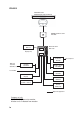
FR-8252 ANTENNA UNIT RSB-0073-087-XN12A/XN13A POWER SUPPLY UNIT PSU-008 Auto Plotter ARP-11 DISPLAY UNIT RDP-150 (built in display unit) RGB Gyro Converter AD-100 100/110/ 115/220/ 230 VAC, 1φ Rectifier RU-3423 12-24 VDC Heading Sensor PG-1000 NMEA DEVICE Remote Display NMEA DEVICE Commercial Monitor (SVGA or better) External Buzzer OP03-136 : Optional equipment Category of units Antenna unit: Exposed to weather All other units: Protected from weather iv Gyrocompass
EQUIPMENT LISTS Standard Supply Name Type Code No.
Optional Supply Name Type Code No. Remarks External buzzer OP03-136 000-086-443 See ch. 4. Rectifier RU-3423 000-030-443 For AC ship’s mains Cable assy.
1. MOUNTING 1.1 Antenna Unit Mounting considerations • The antenna unit is generally installed either on top of the wheelhouse or on the radar mast on a suitable platform. Locate the antenna unit where there is a good all-round view. Any obstruction will cause shadow and blind sectors.
1. MOUNTING Mounting procedure Referring to the outline drawing at the back of this manual, drill five holes in the mounting platform: four holes of 15 mm diameter for fixing the antenna unit and one hole of 25-30 mm diameter for the signal cable. Fastening the radiator to the radiator bracket For your reference, the antenna installation materials list appears in the packing list at the back of this manual. 1. Remove the radiator cap from the radiator bracket. 2.
1. MOUNTING Mounting the antenna unit The antenna unit can be mounted using the fixing holes on the outside (200x200 mm) or inside (140x150 mm) the antenna unit. Using outside fixing holes of the antenna housing Use the hex head bolts (supplied) to mount the antenna unit as below. 1. Lay the corrosion-proof rubber mat (supplied) on the mounting platform. Rubber mat Location of rubber mat 2. Lay the antenna unit on the mounting platform, orienting it as shown in below.
1. MOUNTING 3. Insert four hex bolts (M12x60, supplied) and seal washers (Ф30, supplied) from the top of the antenna housing, as shown below. Hex bolt Seal washer Flat washer Spring washer Nut Fixing the antenna unit chassis 4. Pass flat washers (M12, supplied), spring washers (M12, supplied) and nuts (M12, supplied) onto hex bolts. Fasten by tightening nuts. Do not fasten by tightening the hex bolts; seal washers may be damaged.
1. MOUNTING 8. Coat ground terminal and ground point with silicone sealant as shown below. Hex bolt Flat washer Ground wire Silicone sealant Flat washer Spring washer Hex nut OR GROUND POINT Hex nut Spring washer Flat washer Hex nut Ground wire Weld here.
1. MOUNTING Using inside fixing holes of the antenna housing This method requires removal of the RF unit in the antenna unit to access inside fixing holes. Use hex head bolts, flat washers, spring washers and nuts (local supply) to mount the antenna unit, confirming length of bolts. 1. 2. 3. 4. 5. Unfasten four antenna bolts on the cover to open the antenna unit. Unfasten four screws on the RTB cover to remove it. Unplug connector J827 and J834 on the RTB board.
1. MOUNTING Connecting the signal cable Only the signal cable runs from the display unit (power supply unit in case of FR-8252) to the antenna unit. In order to minimize the chance of picking up electrical interference, avoid where possible routing the signal cable near other onboard electrical equipment. Also, avoid running the cable in parallel with power cables. Pass the cable through the hole and apply sealing compound around the hole for waterproofing.
1. MOUNTING • Connecting the signal cable 1. Open the antenna cover by loosening four bolts, and then fix the stay. Cable entry RTB board cover Antenna unit chassis, cover opened 2. Unfasten the cable gland assembly (plate, gasket, flat washer). The plate may be discarded. 3. Pass the signal cable with connector through the bottom of the antenna unit chassis. Pass the cable through the gland assembly as shown below.
1. MOUNTING 5. Fasten the shielded part of the signal cable with shield clamp (installation material) as shown below. Shield clamp Signal cable Fix shield wire with bolt. Gasket support Cable Entry How to fix signal cable in cable gland 6. Unfasten four screws to remove the RTB board cover. 7. Connect the plugs of the signal cable to the RTB board. FR-8062, FR-8122: J821, J823, J824, J822 FR-8252: J821, J823, J824, J820 RTB board J820 J823 J822 J824 J821 Connecting to the RTB board 8.
1. MOUNTING 9. Attach three EMI cores to the signal cable as shown below. EMI Core RFC-13 (2 pcs) EMI Core RFC-H13 (1 pc) Antenna unit chassis, cover opened 10. Fix the signal cable with the cable clamp as follows. a) Dismount the cable clamp plate and remove clamp and gasket. Remove gasket. Cable clamp plate Remove clamp.
1. MOUNTING b) Run the signal cable as shown below. c) Fix the signal cable with cable clamp as shown below. Cable clamp RTB board cover Top view 11. Release the stay and close the cover. Loosely fasten the antenna bolts; you will have to make some adjustments inside after completion of wiring. Note: When closing the cover, set the gaskets to grooves in the bottom chassis, then tighten bolts. BOTTOM CHASSIS GROOVE GASKET ANTENNA BOLT Torque : 9.8 ±0.1 N .
1. MOUNTING 1.2 Display Unit The display unit can be mounted on a tabletop, on the overhead or flush mounted in a console or panel. Mounting considerations When selecting a mounting location for the display unit, keep the following in mind: • Keep the display unit out of direct sunlight. • The temperature and humidity at the mounting location should be moderate and stable. • Locate the unit away from exhaust pipes and vents. • The mounting location should be well ventilated.
1. MOUNTING Mounting procedure Tabletop mounting Follow the procedure below to mount the display unit on a tabletop. 1. Fix the hanger by using four self-tapping screws (5x20). 2. Screw knob bolts in display unit, set it to the hanger, and tighten the knob bolts. Fix with four self-tapping screws. Hanger Knob Mounting dimensions of display unit Overhead mounting Note: For the overhead mounting, reinforce the mounting location and secure the hanger, with bolts, nuts and washers (local supply).
1. MOUNTING Flush mounting 1. Prepare a cutout in the mounting location whose dimensions are as shown below. 2. Detach two rubber cushions from the display unit. 3. Insert the flush mounting sponge and four threaded rods from the rear side of the display unit, and then set the display unit to the mounting location. 4. Fix the display unit by using four wing nuts from the rear side of the display unit. 200±0.5 292±1 Detach two rubber cushions. Threaded rod Wing nut 282±1.0 303±0.
1. MOUNTING 1.3 Power Supply Unit A power supply unit is shipped with the FR-8252, because of its high power consumption. The power supply unit can be installed almost anywhere provided the location is dry, well-ventilated, sufficient maintenance space is provided and is installed within 5 m (cable length) from the display unit. To fix the unit, use four self-tapping screws (5x20). Note: Do not install the power supply unit on the overhead; install it on the deck or bulkhead. 13 22.5 333 370 ± 0.
1. MOUNTING This page is intentionally left blank.
2. WIRING 2.
2. WIRING 2.2 Wiring the Power Supply Unit Cabling 1. Unfasten four screws to remove the cable clamp. 2. Unfasten four screws to remove the cover. 3. Attach the connectors of three cables as shown in the figure below. POWER Board 03P9419 J11 V H 2 J4 J13 V H 4 V H 5 J3 J1 3P V H 9 VL3P-VV-S2X 2C-AA050 cable (to 12-24 VDC) J5 N H 13 J12 V H 1 0 J14 N H 1 4 Ground terminal MJ-B24 LPF0011-050 cable (to display unit) Antenna cable RW-9771 (03S9771) 4.
2. WIRING Jumper block, slide switch setting The jumper block JP1 and slide switch S112 on the PWR board (03P9419) must be set according to radar model. Open the unit, locate JP1 and S112 and set them as below. Jumper block JP1 ("short" for FR-8252 radar; remove dummy connector and attach connector assy. XH2P-L40-ACR.
2. WIRING 2.3 Port for External Devices External equipments can be connected here as shown below. NMEA1(7P) NMEA2(7P) NMEA sentence device NMEA sentence device HDG (6P) Heading sensor PC/EXT-BUZZER (7P) External buzzer, PC, etc. This equipment can receive the following NMEA 0183 format sentences from other equipment. You will need the optional NMEA cable to connect with external equipment.
3. SETTING UP THE EQUIPMENT 3.1 Setting Language At the first power application after installation, choose a language as follows. 1. Press /BRILL key to turn the power on. “Now Initializing…” appears and after a while the window below appears. Language Language Language Language Language Language Language Language Language Language Language Language English Francais Espanol Deutsch Italiano Portugues Dansk Svensk Norsk Chinese Japanese Thai 2.
3. SETTING UP THE EQUIPMENT 3.2 Opening the Installation Menu After you have installed the equipment, set it up as follows. 1. Press the MENU key. The main menu appears on the screen. 2. Rotate the trackball downward to choose Installation. The installation menu appears in gray to right side of the screen. 3. While pressing down the CANCEL/HL OFF key, press the MENU key five times to activate the Installation menu.
3. SETTING UP THE EQUIPMENT View Position: Choose the operating position for this radar among Left, Left-Center, Center, Right-Center and Right to view echo colors correctly. The default setting is Center. Left: When operating this radar at the left side. Left-Center: When operating this radar at the left-center side. Center: When operating this radar at center position. Right-Center: When operating this radar at the right-center side. Right: When operating this radar at the right side. Approx.
3. SETTING UP THE EQUIPMENT 2. Transmit the radar at 0.25 nm range and measure the bearing of that target relative to ship’s heading with an EBL. 3. Open the Installation menu, and choose Heading Adjust. 4. Press the ENTER key to show the HEADING ADJUST window. S 0° S (0 ° ∼ 359 °) 5. Rotate the trackball upward or downward to set the value measured at the step 2 above. Confirm that the target shows dead ahead on the screen. 6. Press the ENTER key to conclude the setting.
3. SETTING UP THE EQUIPMENT Manual Timing Adjust This adjustment ensures proper radar performance, especially on short ranges. The radar measures the time required for a transmitted echo to travel to the target and return to the source. The received echo appears on the display based on this time. Thus, at the instant the transmitter is fired, the sweep should start from the center of the display (sometimes called sweep origin.
3. SETTING UP THE EQUIPMENT Manual MBS Adjust Main bang (black hole), which appears at the display center on short ranges, can be suppressed as follows. 1. 2. 3. 4. 5. Transmit the radar on the short range. Open the Installation menu and choose Manual MBS Adjust. Press the ENTER key to show the setting window. Rotate the trackball to suppress main bang (between 0 and 255). Press the ENTER key to finish. Video Initial Adjust After completing Auto Installation Setup, you can fine tune the video signal. 1.
4. OPTIONAL EQUIPMENT 4.1 ARP Kit ARP-11 The ARP kit provides automatic radar plotter functions to this radar. Necessary parts Name: ARP kit Type: ARP-11 Code no.: 008-523-050 Contents of ARP kit Name ARP Board Pan head screw Spacer* Spring washer* Type 18P9013 M3x6 C2700W SQ9 SQ15 M3 C5191W Code No. 008-559-080 000-163-189-10 000-159-320-10 000-159-299-10 000-864-204 Qty 1 4 1 3 3 *Not used 1. Unscrew all connector nuts at the rear of the display unit. 2.
4. OPTIONAL EQUIPMENT 4. Mount the ARP board, mating with connectors and fixing it with four screws at the location as shown in the figure below. ARP board 5. Remount 03P9415 and 03P9413 at original position and display cover. Note: After connecting the harness to J601 on 03P9413, bend the harness so that it does not touch the parts on ARP board. 03P9413 J601 ARP board Shall not touch.
4. OPTIONAL EQUIPMENT 4.2 External Monitor You can display the radar image on an external monitor which accepts industrial standard VGA input using the optional RGB kit OP03-195. Supply monitor and interconnection cable (with HD-15P connectors of male, three rows of 15 pins) locally. Necessary parts for external monitor Name: RGB kit Type: OP03-195 Code No.: 008-553-110 Name Type Code No. RGB board 03P9492 008-553-680 Flat cable SML2SC34-4X50BDP.
4. OPTIONAL EQUIPMENT 6. Detach LCD panel from the above assembly. Be sure to disconnect the connector and flat cables. 7. Connect the cable assy. 15SDS/XHP10-005 to the rear side of the RGB board. 8. Fix the shield wire of the cable assy. with a screw used to fix the RGB board. 9. Attach the EMI core RFC-1 to the cable assy. closely to the connector. 10. Pass the signal cable through the hole shown below and then pass it through the “OPTION” port at the rear of the display unit..
4. OPTIONAL EQUIPMENT 4.3 Remote Display The FURUNO Display Unit FMD-811, MODEL1832 or GD-280/380, etc. can be connected to this radar as a sub display. The display unit RDP-150 also can be used as a sub display. To interconnect them, use optional cable MJ-B24LPF0008-100/200/300 (see page iv). Also, the EMI core (option) should be attached to the remote display cable to prevent noise. Installation materials for remote display (Type: CP03-31001、Code number: 008-556-830) Name Type Code no.
4. OPTIONAL EQUIPMENT 7. Fix the signal cable to the spacer of the FIL board with a cable tie CV-150N. Fix the cable to the spacer of FIL board with cable-tie. 8. Reassemble the display unit.
4. OPTIONAL EQUIPMENT 4.4 External Buzzer The optional external buzzer provides a louder alert when an alarm is violated. External buzzer Type: OP03-136 Code no.: 000-086-443 Further, you need the optional cable assy. MJ-A7SPF0007-050C (w/7P connector, 5 m, code no. 000-154-028-10). 1. Attach the MJ-A7SPF0007-050C cable assy. (option) to the PC/EXT-BUZZER port at the rear of the display unit. 2. Cut off the XH connector and cable itself (as necessary) at the end of the external buzzer cable. 3.
4. OPTIONAL EQUIPMENT This page is intentionally left blank.
NAME DOCUMENT 000-153-768-1* J32-00501-* 000-161-509-1* C32-00601-* 000-154-025-10 1 1 Q'TY (*1) 1 1 1 1 1 CP03-30900 ** MJ-A3SPF0018-050ZC 008-554-600-00 CP03-30902 008-553-050-00 CP03-30901 008-553-040-00 SP03-15401 000-090-462-00 RDP-150-J/E DESCRIPTION/CODE № RDP-150-J/E (略図の寸法は、参考値です。 DIMENSIONS IN DRAWING FOR REFERENCE ONLY.) (*1)の書類は、和文仕様専用 (*1) MARKED DOCUMENTS ARE FOR JAPANESE SET ONLY.
0 # / ' 1 7 6 . + 0 ' +056#..#6+10 /#6'4+#.5 70+6 %2 45$ &'5%4+26+10 %1&' ͳ )6 : 㧔⇛࿑ߩኸᴺߪޔෳ⠨୯ߢߔ& ޕ+/'05+105 +0 &4#9+0) (14 4'('4'0%' 10.; 㧕 䍘㪄䍢䍼⇟ภᧃየ䈱㪲㪁㪁㪴䈲䇮ㆬᛯຠ䈱ઍ䍘䍎䍢䍼䉕䈚䉁䈜䇯 㪚㪦㪛㪜㩷㪥㪬㪤㪙㪜㪩㩷㪜㪥㪛㪠㪥㪞㩷㪮㪠㪫㪟㩷㩹㪁㪁㩹㩷㪠㪥㪛㪠㪚㪘㪫㪜㪪㩷㪫㪟㪜㩷㪚㪦㪛㪜㩷㪥㪬㪤㪙㪜㪩㩷㪦㪝㩷㪩㪜㪧㪩㪜㪪㪜㪥㪫㪘㪫㪠㪭㪜㩷㪤㪘㪫㪜㪩㪠㪘㪣㪅 #06'00# +056#..#6+10 /#6'4+#.
%2 6;2' 9#5*'4 *'#& 5%4'9 㩏㩗㩨㩈㩛㩇㩒㩆㩨$ *': $1.6 ⷺ㩘㩨㩣㩎㧔ో㩒㩆㩨㧕 524+0) 9#5*'4 㩔㩨㩒ᐳ㊄ (.#6 9#5*'4 㩚㩀㩨㩁ᐔᐳ㊄ *': 076 ⷺ㩏㨹㩎ޓ㧝⒳ %#2 㩁㨶㨹㩖㩩 5*+'.& %.#/2 㩆㨺㩣㩎㩨㩂㩡㩧㩖㩩 )#5-'6 5722146 㩔㩩㨹㩁㩧㨿㩅㨾 %14415+10 2411( 47$$'4 /#6 㒐ⲁࠧࡓ 5'#.
6*4'#&'& 41& ኸಾ㩘㩨㩣㩎 524+0) 9#5*'4 㩔㩨㩒ᐳ㊄ (.#6 9#5*'4 㩚㩀㩨㩁ᐔᐳ㊄ 9+0) 076 ಄㑆ㅧⲔ㩏㨹㩎 5'.
⇟ ภ 01 %#$.' #55; 㩃㨺㩖㩨㩣⚵ຠ/, %#$.' #55; 㩃㨺㩖㩨㩣⚵ຠ/, %#$.' #55; 㩃㨺㩖㩨㩣⚵ຠ/, %#$.' #55; 㩃㨺㩖㩨㩣⚵ຠ/, ⇛ޓޓ࿑ 176.+0' %1&' 01 /, $ .2( %1&' 01 /, $ .2( %1&' 01 /, $ .2( %1&' 01 /, $ .2( ဳฬ㧛ⷙᩰ &'5%4+26+105 ᢙ㊂ 3 6; )6 : ㆬᛯޓޓޓޓޓޓޓޓ 61 $' 5'.'%6 ㆬᛯޓޓޓޓޓޓޓޓ 61 $' 5'.'%6 ㆬᛯޓޓޓޓޓޓޓޓ 61 $' 5'.'%6 ㆬᛯޓޓޓޓޓޓޓޓ 61 $' 5'.
1 7 6 . + 0 ' &1%7/'06 +056#..#6+10 /#6'4+#.5 52#4' 2#465 70+6 %2 % % %2 /, $ .2( 8. 2 88 5 : % ## 52 257 &'5%4+26+10 %1&' ͳ #8 : 㧔⇛࿑ߩኸᴺߪޔෳ⠨୯ߢߔ& ޕ+/'05+105 +0 &4#9+0) (14 4'('4'0%' 10.; 㧕 016+%' (14 (75' 4'2.#%'/'06 㩕㨷㨺㩇㩨ᄌᦝߩ߅㗿 +06'40#. 5'66+0) ,4 '0 ⸳ቯⷐ㗔ᦠ ࿑ᦠ +056#..#6+10 /#6'4+#.5 Ꮏ᧚ᢱ %#$.' #55; 㩃㨺㩖㩨㩣⚵ຠ/, %#$.
(75' 㩕㨷㨺㩇㩨 (75' 㩕㨷㨺㩇㩨 ()$1 # #% 8 ()$ 8 # 2$( ()$1 # #% 8 ()$ 8 # 2$( 2'4 8'5 (75' 㩀㩧㨼㩢㩕㨷㨺㩇㩨 (75' 㩕㨷㨺㩇㩨 (75' 㩕㨷㨺㩇㩨 ()$1 # #% 8 ()$1 8 # 2$( ()$1 # #% 8 ()$ 8 # 2$( ()$1 # #% 8 ()$ 8 # 2$( &9) 01 14 6;2' 01 2'4 8'5 5'65 2'4 8'55'.
Y.
Y.
Y.
Y.
Y.
1 2 MJ-A3SPF0018-050ZC,5m,φ10 12-24 VDC *1 DPYC-2.5 100/110/220/ 230VAC 50/60Hz,1φ 1 2 A 整流器 24V RECTIFIER + 5 RU-3423 - 6 *2 *1 IV-2sq. 3 *4 10A:24V MJ-A3SPFZ 15A:12V 1 シロ WHT 2 クロ BLK 3 (+) POWER (-) GND *5 19S1004,0.5m 1 2 3 4 5 6 7 8 9 10 *5 MJ-B24LPF0008-100/200/300, 10/20/30m,φ11.
D C B A GND *1 IV-2sq. D-SUB 15P 造船所手配。 オプション。 シールドは完全に接地する。 コネクタは工場にて取付済み。 EMIコアを取り付ける。 外部ブザー *2 EXT. BUZZER OP03-136 シロ アオ キ ミド アカ クロ MJ-A7SPF0007-050C,5m,φ7シロ アオ キ ミド アカ クロ *4. CONNECTOR PLUG FITTED AT FACTORY. *5. ATTACH EMI CORES. *5 MJ-A7SPF0007-050C,シロ 5m,φ7 アオ キ ミド アカ RED アカ クロ BLK クロ *4 MJ-A7SPF WHT 1 BLU 2 YEL 3 GRN 4 RED 5 BLK 6 7 1 2 3 4 5 6 *4 MJ-A7SPF WHT 1 BLU 2 YEL 3 GRN 4 5 RED 6 BLK 7 *4 MJ-A7SPF WHT 1 BLU 2 YEL 3 GRN 4 RED 5 BLK 6 7 *5 SD RD REMOTE-KEY NC +12V EXT.