Multimedia Amp M1 AUDAC PROFESSIONAL AUDIO EQUIPMENT Multimedia Amplifier M1 User Manual & Installation Guide
AUDAC PR OF ES S I ONAL AUDI O EQUI P MENT User Manual & Installation Guide AUDAC http://www.audac.be info@audac.
Index INTRODUCTION ................................................................................................................................................................................................................................................................ 3 ENVIRONMENT ..............................................................................................................................................................................................................................
Introduction This section describes briefly the functionality of the M1amplifier. T he M1 Multimedia Amplifier is developed as a “all in one”, flexible solution for multipurpose use. During the development of the M1, the AUDAC-engineers wanted to achieve four goals: - Delivering a flexible audio solution for multi purposes.
1 Chapter Environment Do not place this unit in an enclosed environment such as a bookshelf or closet. Ensure there is adequate ventilation to cool the unit. Do not block the ventilation openings. Do not place the unit in environments which contain high levels of dust, heat, moisture or vibration. Do not use the unit near water or other liquids. Make sure no water or other liquids can be spilled, dripped or splashed on the unit. The unit is developed for indoor use only. Do not use the unit outdoors.
Safety Requirements Always handle the unit with care. Only use a grounded socket outlet and a power cord with grounding plug to plug in the unit. This unit is not a toy. It should not be operated by children. Do not stick objects through the ventilation openings of the M1. Do not open the unit. (risk for electrical shock) The M1 contains several ‘jumpers’ which can be set. These settings may only be done by qualified people. G CAUTION - SERVICING This unit contains no user serviceable parts.
Pin connections on Connectors XLR (input, output): pin1=Ground, pin2= hot(s+), pin3=cold(s-) Cinch: tip= Signal (left or right), Ring= Ground RJ45 (RS485) Wall panel: Pin 1 White-Orange / Pin 2 Orange / Pin 3 White-Green +12V DC Pin 4 Blue RS485 A Pin 5 White-Blue RS485 B Pin 6 Green Pin 7 White-Brown / Pin 8 Brown / GND Speakon (Left, Amplified Outputs Zone 1 and 2): pin1+ = left out, pin1- = gnd, pin2+ = right out, pin2- = gnd Speakon (Right, Amplified Outputs Zone 1 and 2): pin1+
2 Chapter Overview front and rear panel of the M1 FRONT: REAR: 7
Overview Inputs 1-6 (Mic./St.
Overview Input 7-10 (4x St.
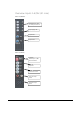
Overview Output Zones OUTPUT ZONES 1-4 (FRONT) Output Level VU-Bar Two band tone control Zone output volume OUTPUT ZONES 1-4 (REAR) Balanced Line Level Outputs (XLR): 4 Zones Stereo Powered Outputs (Speakon) Amp: 2 x 150W stereo (Not available on the M1 Light) 10
Overview DATA Control Ports DATA CONTROL PART (Rear) Ethernet connection (RJ45) Wall Panel Outlets (RS485) Serial Control Port (RS232) Input Priority settings 11
3 Chapter Getting Started When turning on the power, the M1 start-up procedure will take place. This will take about 30sec.. Selected zones will light up green. One of the 4 line sources on ch 7-10 will light up. You can route an Input to a specific Zone Output simply by pressing the routing button once. By pressing the button a second time, the routing will be cleared. Balance and volume from the Input Channels can be changed on the front panel.
Special functions SAVE SETTINGS Routing settings can be saved by pressing together the ‘ch7’ and ‘ch8’ buttons on the front panel of the M1. Hold down the 2 buttons for a few seconds. RECALL SETTINGS Recalling the saved routing settings can be done by pressing together the ‘ch9’ and ‘ch10’ buttons on the M1 front panel. Hold down the 2 buttons for a few seconds.
4 Chapter Wire up the System The AUDAC M1 amplifier is very easy in use. Following cable specs must be followed to guarantee a correct operation: 1. Speaker Cable: minimum 2x1.5 mm2 (distance >15m: 2x2.5mm2) 2. Wall Mounted Panel: UTP/FTP Cat5 cable 3. Music sources: must be connected with audio cable of good quality 4.
Notebook Pocket PC Amplifier 1 Ethernet XLR, Left XLR, Right Wireless Amplifier 2 Wall panel 1 XLR, Left XLR, Right Wall panel 2 Wireless Router RS485 RS485 Ethernet L R XLR Microphone 1 XLR Microphone 2 RS232 R L L+R Tuner R L L R Sub CD player Home automation systems 15
Bridge Mode The M1 Multimedia amplifier can also be set in bridged mode (300W / 8ohm) by setting some jumpers on the inside of the M1. This has to be done by qualified people !! In the following paragraphs the proper wiring for a bridged M1 stereo setup is explained. Connect the left output channel of the audio source to the left channel of an input channel of the M1. Connect the right channel of the audio source to the left channel of another input channel of the M1.
5 Chapter Remote Control Interface To use the remote control interface, the M1 has to be plugged in to an Ethernet LAN network with a standard (straight) network cable. Make sure the M1 default network address (192.168.0.180) is within range of the connected Ethernet LAN network ! If the M1 default network address is not within range of your LAN network, contact your network specialist.
Standard Web Based User Interface LOG-IN SCREEN: When you surf to the webpage of the M1, you will see the logon screen of the M1. Default the IP address is http://192.168.0.180 You will have to enter a user name and password to get access.
CONTROL SCREEN: If you press “enter” after typing the correct username and password, you get access to the control screen of the M1. After logging in, the “Connection Status” will indicate “online” if a connection with the M1 has been made. Following changes can be made: routing, volume settings of input channels and output zones, source selecting on ch 7-10, channel/zone muting.
CONFIGURATION SCREEN: This window will be opened after pressing the “Configuration” button in the control window. (Default Username: audac, default password: M1) In this window the IP address can be changed and DHCP can be enabled. The user name and password and the administrator name and password can be changed. There is a secret “rescue” password in case of emergency (passwords lost). This can be asked at info@audac.be . After each change of settings, press the corresponding “Change Settings” button.
6 Chapter Lite Web Based User interface PURPOSE: The purpose of the Lite Web Based User Interface is to offer easy access to the basic functions of the M1 and to offer access to the M1 on devices with a small screen, e.g. pocket PC’s, PDA’s, GSM’s … ACCESS: To access the Lite Web Based User Interface you will need a web browser with the “Macromedia Flash Player 6 ” or “Macromedia Flash Player 6 for pocket PC 2003” plug-in installed. The Lite Web Based User Interface can be accessed by typing “/small.
ROOM CONFIGURATION SCREEN: In this screen you can assign an input source to the selected room, change the output volume ( = zone output volume) or mute the output volume. To configure another room or to go back to the “ Start-up Screen “, press on the name of the selected room. To change the names of the input sources and/or the rooms, press 3 times the “ Audac “ logo on the bottom of the screen.
NAME CONFIGURATION SCREEN: This screen can be activated by pressing 3 times on the “Audac” logo in the “Room Configuration Screen”. Here you can change the names of the “ Rooms“ and the names of the “ Input Sources“. By pressing the “ – “ and the “ + “ buttons on the screen you can navigate throughout the list of room names and input source names. By placing the cursor in the field and using the keyboard you can change the names to your flavour. When the changes are made, press the “ Save” button.
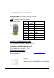
7 Chapter Wall Mounted Control Panels (Optional) The M1 Multimedia amplifier can be equipped with wall mounted control panels on each zone output. A zone output can be controlled by more then one wall mounted control panel. The maximum number of wall mounted control panels connected to the M1 multimedia amplifier is 4. These wall mounted control panels are controlled by an RS485 data bus and must be connected with the M1 with “twisted pair” or “CAT5” cable.
Jumper settings for zone output selection A B C D E 25 A J J J J B J J J J C D E Zone output J J J 1 J J 2 J J 3 J 4 J = set jumper
Additional Information M1 TECHNICAL SPECIFICATIONS Sensitivity Microphone input Line input -60/-20 dB 600 Ohm balanced -20/+4 dB 10k Ohm Frequency response T.H.D. by 1 kHz Signal to Noise ratio Slew rate 20 Hz – 20 kHz less than 0.1% 90 dB +/- 30V/µsec Digital control Remote zone control Web based control RS-232 RS-485 Ethernet Zone outputs 1-4 +6dB 100 Ohm Balanced Output power per channel 100 Watt 8 Ohm 150 Watt 4 Ohm 300 Watt 8 Ohm Bridge mode Power Supply Max.
Personal Notes 27