Back COLOR DGPS/PLOTTER COLOR GPS/PLOTTER GP-1650D, GP-1650 FURUNO/NAVIONICS GP-1650D, GP-1650 FURUNO/C-MAP NT
C Your Local Agent/Dealer 9-52, Ashihara -cho, Nishinomiya, Japan Telephone: Telefax: 0 7 9 8 - 6 5 - 2111 0798-65-4200 All rights reserved. Printed in Japan P U B . N o . O M E -4 3 9 4 0 ( DAMI ) GP-1650/1650D FIRST EDITION N3 : : FEB .
SAFETY INSTRUCTIONS CAUTION WARNING Do not use the equipment for other than its intended purpose. Do not open the equipment. Hazardous voltage which can cause electrical shock, burn or serious injury exists inside the equipment. Only qualified personnel should work inside the equipment. Use of the equipment as a stepping stool, for example, can result in personal injury or equipment damage. No one navigation device should ever be solely replied upon for the navigation of a vessel.
TABLE OF CONTENTS FOREWORD ....................................... iv SYSTEM CONFIGURATION ....... v 5. WAYPOINTS 5.1 5.2 5.3 5.4 5.5 Entering Waypoints.......................... 5-1 Erasing Individual Waypoints ......... 5-4 Changing Waypoint Data ................. 5-4 Waypoint Mark Size ......................... 5-5 Changing Waypoint Position on the Plotter Display ................................. 5-5 5.6 Searching Waypoints ....................... 5-5 1. OPERATIONAL OVERVIEW 1.1 1.2 1.3 1.4 1.5 1.
10. CUSTOMIZING YOUR UNIT 10.1 10.2 10.3 10.4 CHART SETUP OPTIONS menu .. 10-1 DISPLAY OPTIONS menu ............. 10-2 GPS/DGPS/TD OPTIONS menu ... 10-4 CONFIGURATION menu ............... 10-7 11.USING C-MAP NT MODEL 11.1 Inserting Chart Card ........................11-1 11.2 Cussor and Data Display ................11-1 11.3 Tidal Information .............................. 11-2 11.4 Navigation to Ports, Port Services ..11-3 11.5 Setting Chart Setup Options ...........11-5 11.
FOREWORD A Word to GP-1650D/1650 Owners Features The GP-1650D is a totally integrated DGPS beacon receiver, GPS receiver, and color video plotter. The GP-1650 mostly shares the same features with the GP-1650D except it does not have a built-in DGPS beacon receiver. Congratulations on your choice of the FURUNO GP-1650D COLOR DGPS/PLOTTER, GP-1650 COLOR GPS/PLOTTER. We are confident you will see why the FURUNO name has become synonymous with quality and reliability.
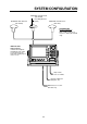
SYSTEM CONFIGURATION ANTENNA UNIT GPA-018 (GP-1650D) ANTENNA UNIT GPA-019 (GP-1650D) 1.2 m Whip Antenna (option) ANTENNA UNIT GPA-017 (GP-1650) ANTENNA UNIT Receives signal from GPS satellite and beacon reference station (GP-1650D only). DISPLAY UNIT Ship’s position is calculated in longitude and latitude from signal received from the antenna unit and displayed on the screen. Ship’s mains 10.8—31.2 VDC External equipment (Autopilot, etc.
This page is intentionally left blank.
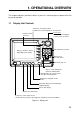
1. OPERATIONAL OVERVIEW This chapter acquaints you with the basics of your unit - from turning on the power to the soft key menu operation. 1.1 Display Unit Controls • Registers own ship's position. • Marks man overboard position, event position. Cursor pad • Shifts cursor and display. Registers items on menus. • Selects items on menus. SAVE MOB ENTER Soft key's functions change depending on the display.
1.2 Inserting Mini Chart Card Insert appropriate mini chart card before turning on the power. 1. Push down the lid catch to open the mini chart card slot cover. Your equipment takes about 90 seconds to find its position when turned on for the very first time. This is because the equipment has no satellite data, called the Almanac, in its database.
1.4 Adjusting Tone and Brilliance NORTH UP ZOOM IN ZOOM OUT 1. Press the [POWER/BRILL] key with a touch-and-release action. The tone and brilliance setting menu appears. COURSE UP WP-002 FISH Functions BRIDGE NAV POS DGPS 3D [Plotter Display] TONE TONE TONE DATE: OCT 21 1998 POSITION BRILL BRILL TIME 23:59:59 LAT/LON 34° 56.789’ N 135° 56.789’ E BRILL SPD TD RNG 16.3 RETURN LAT LON 27.2 NM KT CSE ZOOM BRG 245.8° 245.
Steering display, Highway display MENU CHART SETUP OPTIONS Press the [XTE/HIWAY] key to display the Steering display, Highway display alternately. DISPLAY OPTIONS Soft keys GPS/DGPS/TD OPTIONS CROSS TRACK QP<01> 230 240 27.2 13.6 RNG SPD ETA 1h 59m 0.1NM 260 Figure 1-7 Main menu 245.0° 234.5° BRG CSE TTG 250 CONFIGURATION DGPS 3D XTE nm kt 29th 14:50 000. 02nm DGPS 3D 0.1NM EDIT XT- LMT 2. Press appropriate soft key to display desired menu.
4. Use the cursor pad to select item, and then press the soft key EDIT. For example, select TRACK COLOR. The track color window appears. 4. Press the soft key labeled EDIT to show the demo mode window. DEMO MODE TRACK COLOR ▲ ▲ ' ON ™ OFF ▼ RED ™ YELLOW ™ GREEN ™ LIGHT BLUE ™ PURPLE ™ BLUE ™ WHITE ▼ ' Figure 1-13 Demo mode window 5. Press ▲ to select ON. Figure 1-10 Track color window 5. Use the cursor pad to select option. 6. Press the soft key RETURN to finish. 1.7 3.
This page is intentionally left blank.
2. PLOTTER DISPLAYS 2.1 Course-up Presentation Modes The plotter display mainly shows chart, ship’s track, waypoints, and navigation data. Three types of display presentations are provided for the normal plotter display: north-up, course-up and auto course-up. To change the mode, use the presentation mode selection soft key, which is the 3rd soft key from the top. North-up Press the soft key COURSE UP to show the course-up display.
2.2 Cursor 2.4 Turning on the cursor, shifting the cursor Press the cursor pad to turn the cursor on, and the cursor appears at the own ship’s position. Operate the cursor pad to shift the cursor. The cursor moves in the direction of the arrow or diagonal pressed on the cursor pad. Cursor state determines what data is shown on the display. Cursor position is displayed in latitude and longitude or Loran or Decca TDs (depending on menu setting) at the top of the plotter display when the cursor is on.
Indices and chart enlargement Chart symbols When the soft key ZOOM OUT is used, you will see several frames appear on the chart. These frames are called indices and they show you what parts of the chart can be enlarged in the current picture range. The areas circumscribed with smaller frames can be enlarged, but the area enclosed by the largest frame cannot. FURUNO mini chart card The table below shows FURUNO mini chart symbols and their meanings.
Table 2-3 Comparison of FURUNO and Nav-Charts™ chart cards Item FURUNO Dot scrolling capability YES Course-up display YES Nav-Charts™ Range and bearing from own ship YES YES Lighthouse data YES *3 presentation YES Zoom at cursor position YES *1 0.125, 0.5, 1, 2... 2048 nm Same as left Chart offset data entry YES YES Centering YES *2 Range at Equator Example of data displayed Period (ex.: 6 seconds) Visibility in nautical mile (ex.: 12 miles) NAVAID: /FL 6S 12M FROM OS 52.38nm 48.
Enlarging an indication Emergency medical service Fueling station Water supply station Traveler’s service station An indication on the screen may be enlarged as follows: 1. Use the cursor pad to select the indication which you wish to enlarge. Selected indication is circumscribed with a red cursor. 2. Press the soft key ZOOM. To return to the normal nav data display, press the soft key RETURN.
Beacon information display 2.7 Equipped with a DGPS beacon receiver, your unit can show DGPS reference station information. Press the soft key BEACON INFO to show the DGPS reference station information. The steering display provides steering information such as range, bearing, ETA to destination, course and speed. DGPS reference station information Receive data status Beacon receiver setting status MODE FREQ BAUD RATE AUTO SEARCH 288.
How to read the XTE scale 2.8 The black boat-shaped mark shows own boat’s movement and direction, and amount to steer to return to course. Using Figure 213 as an example, you would steer right by 000.02 nautical miles to return to course. When this mark is out of range of the XTE scale, the mark color changes from black to yellow. The range of the XTE scale can be set as shown below (default: 0.5 nm). The highway display provides a graphic presentation of ship’s track along intended course.
2.9 Changing Operation Mode Operation mode can be changed between PLEASURE and FISHING. FISHING mode provides mark/line entry on the PLOTTER display. The mark can be entered up to 5000 points together with tracks. The apportion between track and mark memory can be changed at menu. Pressing the [HIDE/ SHOW] key changes the function of soft keys. Holding track, changing track color, and selecting color and form of mark/line can be performed by the soft keys directly. 2.
3. TRACK 3.1 Displaying Track s DISPLAY 1. Press the [MENU] key to open the main menu. MENU TRACK ON TRACK COLOR WHITE PLOT TIME TIME INTERVAL 01m00s DIST INTERVAL 00.10 nm TRACK MEMORY 2000 POINTS (MARK MEMORY) (3000) POINTS TRACK STATUS CHART SETUP OPTIONS TRACKING TRACK : 1000 / 2000 PTS used MARK : 5 / 3000 PTS used DISPLAY OPTIONS TRACK CONTROL EDIT STOP TRACK ERASE TRACK ERASE MARK RETURN GPS/DGPS/TD OPTIONS DGPS 3D Figure 3-3 Track control menu DGPS 3D 4.
3.2 Stopping/Restarting Plotting of Track TRACK COLOR ▲ ' RED ™ YELLOW ™ GREEN ™ LIGHT BLUE ™ PURPLE ™ BLUE ™ WHITE ▼ When your boat is at anchor or returning to port you probably won’t need to record its track. You can stop recording the track, to conserve the track memory, as follows: 1. Press the [MENU] key followed by the soft keys CHART SETUP OPTIONS and TRACK CONTROL. 2. Press the soft key STOP TRACK. The indication “TRACKING” in the TRACK STATUS window changes to “NOT TRACKING”.
PLOT ▲ ' TIME ™ DISTANCE ▼ Figure 3-5 Plot window 4. Press ▲ or ▼ to select TIME or DISTANCE. Distance is useful for conserving track memory, since no track is recorded when the boat is stationary. 5. Press the soft key ENTER or the [ENTER] key. Track plotting interval 1. Press the [MENU] key followed by the soft keys CHART SETUP OPTIONS and TRACK CONTROL. 2. Press ▲ or ▼ to select TIME INTERVAL or DIST INTERVAL. 3.
3.6 Erasing All Track You can erase all track. Be absolutely sure you want to erase all track; erased track cannot be restored. 1. Press the [MENU] key followed by the soft keys CHART SETUP OPTIONS and TRACK CONTROL. 2. Press the soft key ERASE TRACK. You are asked if you sure to erase all track. 3. Press the [ENTER] key to erase, or press the [CLEAR] key to escape.
4. MARK 4.1 Entering Marks Select the fishing mode to enable entry of marks on the PLOTTER display. Select the location desired with the cursor, or turn off the cursor to enter the mark at own ship position. Pressing the [HIDE/SHOW] key changes the function of the soft keys. Press the soft key MARK ENTRY to enter the mark. The mark is entered in the shape and color selected from the MARK SHAPE and MARK COLOR windows.
4.2 Changing Mark Attributes MARK LINE ▲ ' You can select shape, line and color of mark/ line on the TRACK display. ™ ™ ™ ▼ 1. Press the [HIDE/SHOW] key to show the soft key MARK EDIT. 2. Press the soft key MARK EDIT to show the MARK/LINE window. MARK SHAPE . MARK LINE MARK COLOR YELLOW Figure 4-2 MARK/LINE window 3. Press the soft key MARK SHAPE to change mark shape, the soft key MARK LINE to change mark line, or the soft key MARK COLOR to change mark color.
4.3 Changing Mark Size 4.4 Erasing Marks Mark size can be selected from STD (standard) and SMALL. Erasing individual marks/lines 1. Press the [MENU] key to display the main menu. 1. Operate the cursor pad to place the cursor on the mark you want to erase. 2. Press the soft key CHART SETUP OPTIONS. 2. Press the [CLEAR] key. The mark selected is erased. 3. Press the soft key CHART DETAILS to open the CHART DETAILS menu. Note: To erase line, place the cursor on a edge of the line.
This page is intentionally left blank.
5. WAYPOINTS 5.1 Entering Waypoints In navigation terminology, a waypoint is a particular location on a voyage whether it be a starting, intermediate or destination point. A waypoint is the simplest piece of information your equipment requires to get you to a destination, in the shortest distance possible. This unit has 835 waypoints (including quick waypoints) into which you can enter position information.
ADD/EDIT/MOVE WAYPOINTS WPT Changing the shape and color of waypoint mark LOCAL LIST 1. Press the soft key SELECT MARK. ALPHA/NUMERIC LIST 2. Press the soft key MARK SHAPE to open the mark shape selection window. WAYPOINT BY CURSOR WAYPOINT BY RANGE & BEARING MARK SHAPE RETURN DGPS 3D Figure 5-4 waypoint menu 3. Press the soft key WAYPOINT BY CURSOR. The plotter display appears. 4. Operate the cursor pad to place the cursor on the location desired. 5. Press the soft key NEW WPT.
Changing waypoint name, comment, proximity alarm radius 34° 12.345’ N 135° 12.345’ E FROM ’X’ 0.01nm 224.1 WPT RNG BRG ZOOM IN 1. If necessary, you can change the name (1 to 6 characters), comment (13 characters), L/L position and the proximity alarm radius (explained in detail in Chapter 8) as follows: a) Select the NAME, COMMENT or PROXIMITY ALARM RADIUS field. b) Use the cursor pad to select character or digit. c) Enter appropriate data with the alphanumeric keys.
BRG. 23.8° 1.75nm FISH01 RNG. 33°12.345' N ABCDEFGHIJKL WPT LOCAL 135°23.456' W GO TO WPT001 12:30 29SE97 BRG. 90.0° RNG. 2.51nm 33°23.456' N 135°23.567' W BRG. 180.0° 5.07nm ABCDEF RNG. 34°12.345' N 15:21 01OCT97 135°54.321' W BRIDGE BRG. 359.9° RNG. 8.01nm 34°12.345' N 135°54.321' W 16:45 01OCT97 DGPS 3D NEW WPT EDIT WPT BRG. 180.0° 5.07nm ABCDEF RNG. 34°12.345’ N 15:21 01OCT97 135°54.321’ W BRIDGE BRG. 359.9° RNG. 8.01nm 34°12.345’ N 135°54.
5.4 Waypoint Mark Size You may change the size of all waypoint marks to small or large (default), or turn them off. 3. Operate the cursor pad to place the cursor on the waypoint which you want to change. A flashing diamond mark appears on the waypoint when it is correctly selected. 1. Press the [MENU] key to open the main menu. 4. Press the soft key EDIT/MOVE. 2. Press the soft key CHART SETUP OPTIONS. 6. Operate the cursor pad to place the cursor on the location desired. 3.
This page is intentionally left blank.
6. ROUTES Often a trip from one place to another involves several course changes, requiring a series of route points (waypoints) which you navigate to, one after another. The sequence of waypoints leading to the ultimate destination is called a route. Your unit can automatically advance to the next waypoint on a route, so you do not have to change the destination waypoint repeatedly. You can store up to 200 routes. A route may consist of 35 points.
Entering routes by the cursor CONNECT ROUTE This method allows you to construct a route directly on the plotter display, using existing waypoints or new locations. Any new location will be saved as a waypoint, under the next consecutive waypoint number. FIRST SECOND ______ ______ FORWARD REVERSE NEW ROUTE F<-->R SAVE 1. Follow step 1-4 in “Entering routes through the route list.” 2. Press the soft key PLOT. The plotter display appears. DGPS 3D CANCEL Figure 6-3 Connect route window 3.
EDIT ROUTE ROUTE NAME: ABCDEF COMMENT: ABCDEFGHIJKL s 01 WPT001 02 WPT002 03 WPT003 04 WPT004 05 WPT005 34°12.345’N 135°54.321’W 34°23.456’N 136°10.255’W 35°11.222’N 136°55.889’W 35°22.878’N 136°44.333’W 34°15.279’N 135°34.111’W LEG 204.8° 33.83nm 22.0° 34.27nm 35.1° 2.89nm 125.6° 31.25nm INSERT WPT REMOVE WPT CHANGE WPT COORD TYPE RETURN RETURN DGPS 3D 5. Press ▲ or ▼ to place the cursor at the location where you want to insert a waypoint. 6.
Removing route waypoints from the plotter display Next consecutive route number 1. Press the [WPT/RTE] key followed by the soft key ROUTES to open the route menu. ROUTE NAME SAVE ROUTE START LOG 006 2. Press ▲ or ▼ to select the route desired. COMMENT 3. Press the soft key EDIT ROUTE. 4. Press the soft key PLOT to show the plot screen. 5. Operate the cursor pad to place the cursor on the waypoint you want to remove from the route. 6. Press the soft key REMOVE WPT. 6.
NORTH UP ZOOM IN ZOOM OUT COURSE UP DGPS 3D SA VE NAV L/L SAVE icon Figure 6-9 SAVE icon appearance on the plotter display 7. Press the [SAVE/MOB] key with a touchand-release action to enter a waypoint mark at own ship position. A new waypoint is created under the next consecutive waypoint number and that waypoint is added to the route. 8. Repeat step 7 as necessary. 35 waypoints can be entered. 9. Press the [WPT/RTE] key followed by the soft key CREATE VOYAGE BASED ROUTE. 10.
This page is intentionally left blank.
7. NAVIGATION 7.1 Navigating to “Quick Points” The “quick point” feature allows you to navigate to point(s) without retaining the data indefinitely in your unit’s memory. Each time a quick point is entered the previous quick points having the same quick point numbers are written over. Selecting quick point entry method You need to tell your unit how to set the quick point: 1 POINT, 35 POINT (up to 35 points) or WPT/PORT SERV. (For WPT/PORT SERV, see the next page.) 3.
7.2 Navigating to Waypoints (waypoint list) 1. Press the [WPT/RTE] key to open the waypoint & route menu. + 40°45.971’N 13°57.462’E 4. Select a waypoint. 5. Press the soft key GO TO. The plotter display appears. A light-blue line runs between destination selected and own ship’s position. Arrows on the line show the direction to the follow. Waypoint data appear at the top of screen. 0.26 nm 180.2° GO TO QUICK ROUTE NEAR SRVICE PUNTA CORNACCHIA PORT ACCO AMENO 2.
8. If you selected PORT in step 7, use the cursor pad to select a port and press the [ENTER] key. Make a route using the soft keys and press the [ENTER] key. (If you want to go directly to that port, simply press the soft key ADD QP followed by the [ENTER] key.) FISH WPT FROM OS 1.3 nm 208.5° ZOOM IN ZOOM OUT WP-002 GO TO WPT FISH If you selected NEAR SERVICE in step 7, select service mark desired and then press the soft key ENTER. Then, the display shows the locations of those services nearest you.
Restarting navigation Setting speed for ETA calculation When you steer to avoid an obstacle or the vessel drifts, you may go off your intended course (Line 1 in Figure 7-7). Use the steering or highway display to return to course. Speed, which may be input manually or automatically, is required to calculate ETA (Estimated Time of Arrival) to a waypoint.
To select waypoint switching method do the following: 1. Press the [MENU] key. 2. Press the soft key DISPLAY OPTIONS. 3. Select WAYPOINTS SW. 4. Press the soft key EDIT to show the waypoint sw window. 5. Select appropriate waypoint switching method. 7.5 Cancelling Navigation 1. Press the [WPT/RTE] key. 2. Press the soft key LOG. 3. Press the soft key STOP. 4. Press the [ENTER] key to go stand by. 5. Press the soft key RELEASE. 6. Press the [ENTER] key. 6. Press the soft key ENTER to close the window.
This page is intentionally left blank.
8. PLOTTER ALARMS 8.1 4. Press ▲ or ▼ to select ON or OFF. Introduction There are five plotter-related alarms which generate both audible and visual alarms: Arrival alarm, Anchor Watch alarm, XTE (Cross Track Error) alarm, Proximity alarm, and Speed alarm. When an alarm setting is violated the buzzer sounds, and the speaker icon ( ) appears in red. You may silence the alarm by pressing the [CLEAR] key. The icon remains on the screen until the cause of the alarm is removed or the alarm is deactivated. 8.
8.4 Anchor Watch Alarm The anchor watch alarm informs you that your boat is moving when it should be at rest. When the anchor watch is active, a red dashed circle marks the anchor watch area. 8.5 XTE (Cross Track Error) Alarm The XTE alarm warns you when your boat is off its intended course. When the XTE alarm is active two red dashed lines mark the XTE alarm area. Alarm setting Your ship’s position where you start the anchor watch alarm.
8.6 Speed Alarm The speed alarm warns when your boat’s speed is within, over/under or under the speed range set. 1. Press the [ALARM] key to open the alarm menu. 2. Press ▲ or ▼ to select SPEED ALARM. 3. Press the soft key EDIT to display the speed alarm window. SPEED ALARM ▲ ' WITHIN 15.0 ~ 15.3 kt ™ OVER/UNDER ™ OFF ▼ 8.7 Proximity Alarm The proximity alarm alerts you when your vessels nears a waypoint by the distance set for that waypoint on the waypoint list.
8.8 Alarm messages Alarm Information When an alarm setting has been violated the buzzer sounds and the speaker icon (shown in red) appears. You can see which alarm has been violated, as well as silence the buzzer, on the alarm menu display. ALARM ARRIVAL ALARM ANCHOR ALARM PROXMTY ALARM XTE ALARM SPEED ALARM ON ON 0.100nm ON 0.050nm ON ON 0.100nm OVER/UNDER 12.5 ~ 15.0kt ALARM INFORMATION ALARM1 EDIT CLEAR ALARM NEXT PAGE Alarm information (Example: Arrival alarm) Figure 8-11 Alarm menu 2.
9. SAVING AND LOADING DATA TO/FROM MEMORY CARD The following data can be saved to memory card: • Mark/line • Waypoints/routes • Track • Configration (menu settings) 9.1 Before you can use a memory card it must be formatted. Note that formatting a used card erases all saved data. 1. Insert the memory card you want to format into the slot. 2. Press the [MENU] key followed by the soft keys CONFIGRATION and UPLOAD/ DOWNLOAD DATA. MARK/LINE 1. Insert a formatted memory card into the slot. 2.
Error message OVERWRITE FOLLOWING DATA. OK? (TRACK) Memory card not inserted YES ... "ENTER" key NO ... "CLEAR" key Press the [ENTER] key to return to the SAVE DATA display. MEMORY CARD NOT INSERTED. INSERT CARD PRESS "ENTER" key TO CONTINUE. Figure 9-3 NOT INSERTED message Unformatted memory card Press the [ENTER] key to return to the SAVE DATA display. And format it refering to the previous page. MEMORY CARD NOT FORMATTED PRESS "ENTER" key TO CONTINUE.
6. After you select all items desired, press the soft key LOAD DATA to load data. The following message appears. NOW LOADING DATA FROM MEMORY CARD. DO NOT TURN OFF THE POWER UNTIL LOADING COMPLETE. Figure 9-8 LOAD DATA message After loading is completed, the following message appears. COMPLETE LOADING DATA. PRESS "ENTER" KEY TO CONTINUE. Figure 9-9 COMPLETE message 7. Press the [ENTER] key.
This page is intentionally left blank.
10. CUSTOMIZING YOUR UNIT This section describes the various options which allow you to set up your unit to suit your needs. 10.1 CHART SETUP OPTIONS menu The chart offset options menu provides three menus: chart offset, track control, and chart details. 1. Press the [MENU] key to open the main menu. CHART OFFSET menu In some instances position may be off by a few minutes. For example, the position of the ship is shown to be at sea while it is in fact moored at a pier.
CHART DETAILS menu 1. Press the [MENU] key followed by the soft keys CHART SETUP OPTIONS and CHART DETAILS. sLAT/LON GRID TEXT INFO WAYPOINT WAYPOINT NAME INDEX LANDMASS BACKGROUND NAV AIDS SECTOR INFO OTHER SYMBOLS GREEN ON LARGE ON ON BRT YELLOW BLUE ON OFF WHITE DGPS 3D CHART DETAIL EDIT DEPTH INFO NAV AIDS: Turns aids to navigation symbols (for example, buoys) on/off. The default setting is ON. When OFF is selected, symbols are displayed and information is not.
RANGE/SPEED UNIT Selects the unit for range and speed; nm/kt (default setting), km/ km/h, sm/ sm/h. DEPTH UNIT You can display your ship’s course and bearing to waypoint in true or magnetic bearing, and the default setting is magnetic. MAG VARIATION TEMP UNIT The magnetic variations for all areas of the earth are preprogrammed into this unit. The preprogrammed variation is accurate for most instances, however you may wish to manually enter a variation.
SET GO TO METHOD GPS OPTION s LOCAL TIME OFFSET Selects the method for entering the quick point: 1 POINT (default setting), 35 POINT (2-35 points), or WPT/PORT SER. For further details see pages 7-1 and 7-2. OPERATION MODE Selects the operation mode between PLEASURE and FISHING.For further details see page 2-8. GEODETIC DATUMS POS SMOOTHING SPD/CSE SMOOTHING GPS SPEED AVE LAT OFFSET LON OFFSET DISABLE SATELLITE LATITUDE LONGITUDE ANT. HEIGHT FIX MODE +00:00 WGS-84 000 sec 005 sec 060 sec 0.000’N 0.
POS SMOOTHING DISABLE SATELLITE When the DOP or receiving condition is unfavorable, the GPS fix may change greatly, even if the vessel is dead in water. This change can be reduced by smoothing the raw GPS fixes. A setting between 000 to 999 is available. The higher setting the more smoothed the raw data, however too high a setting shows response time to change in latitude and longitude. This is especially noticeable at high ship’s speeds.
DGPS SETUP OPTIONS menu TD SETUP menu This menu sets parameters for the DGPS beacon receiver. (GP-1650D, or GP-1650 equipped with DGPS beacon receiver.) To display it, press the [MENU] key followed by the soft keys GPS/DPGS/TD OPTIONS and DGPS SETUP OPTIONS. This menu selects the Loran C or Decca chain to use to display position in TDs. To display it, press the [MENU] key followed by the soft keys GPS/DPGS/TD OPTIONS and TD SETUP.
SETUP NMEA PORT 1 menu description Displaying DECCA TDs 1. Select DEC CHAIN and press the soft key EDIT to show the chain sta. pair window. CHAIN STA. PAIR ▲ 20 s P-R ▼ FRENCH This menu sets up DATA PORT 1 according to the specifications of the equipment connected to it. The menu can be displayed by pressing the [MENU] key followed by the soft keys CONFIGURATION and SETUP NMEA PORT 1. For detailed information, see the installation manual. Figure 10-12 Chain sta. pair window 2.
SETUP NMEA/DGPS PORT 2 menu description DWNLOAD UPLOAD DOWNLOAD WPT/RTE TO PC This menu should be set according to the specifications of the equipment connected to connectors PORT 1 (NMEA) and PORT 2 (DGPS) at the rear of the display unit. The menu can be displayed by pressing the [MENU] key followed by the soft keys CONFIGURATION and SETUP NMEA PORT 2. For detailed information, see the installation manual.
Download waypoint/route to PC Upload waypoint/route from PC 1. Connect the PC to the equipment as shown below. Note that all waypoint and route data stored in your unit will be deleted when data is uploaded. 2. Press the soft key labeled DOWNLOAD WPT/RTE TO PC. You are asked if you are ready to download waypoints and routes. 3. Press the [ENTER] key to download. 1. Connect the PC to the equipment as shown below. 2. Press the soft key labeled UPLOAD WPT/ RTE FROM PC.
Waypoint data format Route data menu PFEC, GPwpl, llll.llll, a, yyyyy.yyy, a, c----c, c, c----c, a 1 2 3 4 5 6 7 8 $GPRTE, x, x, a, ccc, c----c, c----c, ... , c----c 1 2 3 4 5 6 12 Figure 10-18 Waypoint data format Figure 10-20 route data format 1: Waypoint latitude 1: Number of sentences required for one complete route data (1 to 4). See Note 2.
SYSTEM menu This menu provides testing facilities, demonstration mode setup and memory/trip clear. You may display it by pressing the [MENU] key followed by the soft keys CONFIGURATION and SYSTEM MENU. SYSTEM MENU SELF TEST DEMONSTRATION MODE MEMORY/TRIP CLEAR DGPS 3D RETURN Figure 10-23 System menu SYSTEM MENU description SELF TEST, MEMORY/TRIP CLEAR: SELF TEST and MEMORY/TRIP CLEAR are described in Chapter11. DEMONSTRATION MODE: This sets the parameters for the demonstration display.
This page is intentionally left blank.
11. USING C-MAP NT MODEL The GP-1650D/1650 C-MAP NT series uses FURUNO mini chart card and C-MAP NT-FP chart card. These charts show accurate coastlines, depth contours, place names, aids to navigation such as buoys and lighthouses, and other navigational marks. 11.1 Inserting Chart Card 11.2 Cursor and Data Display Besides its fundamental functions of providing position data, the cursor can also show caution area, depth area, source of data, etc.
4. Press ! or " to select the item desired. Objects 5. Press the soft key ENTER or the [ENTER] key to display details for object selected Objects. Navigation mark, fixed Extended navigational aid, ge Light Light Light Light Depth contour Land area Source of data Caution area Information LEUCHTFEUER DIE KARTE ENTHAEL T NUR DIE LAGEN DER WICHTIGEN FEUER. LIGHTS ONLY THE PRINC IPAL LIGHTS ARE SHOWN ON THIS CHART. MISSWEISUNG SIEHE K ARTEN GROESSEREN MASSSTABS.
2. Press the [ENTER] key to open the Objects window. 7. Press the soft key ENTER or the [ENTER] key to show the tidal graph for entered date. 8. Press or to locate the vertical cursor on the time desired. Time and height are shown to the left of the graph. 9. Press or to shift the level cursor. Draught is shown to the left of the graph. Objects Tide height Depth contour Caution area Depth area Source of data 10. Press the soft key CANCEL to close the TIDE window.
6. Press the soft key GO TO. Soft key titles change as in Figure 11-10. If GO TO key is not displayed, press the cursor pad. + 40˚45.971'N 13˚57.462'E FROM OS 0.26 nm 180.2˚ + 40˚45.971'N 13˚57.462'E FROM OS 0.26 nm 180.2˚ GO TO GO TO PUNTA CORNACCHIA ACCO AMENO QUICK ROUTE NEAR SRVICE CASAMICCIOLA PUNTA CORNACCHIA ACCO AMENO ENTER ISCHIA PORTO DGPS 3D I.SELECT ISCHIA ICON BY KEY. CANCEL GO TO ISCHIA PORTO Figure 11-15 Sample filling station locations CASAMICCIOLA I.
d) Press the [ENTER] key to finish. A line connects between own ship and the port service. And the range and bearing from own ship to first waypoint appears. Note: Destination is automatically cancelled if there is no port for service selected. 11.5 Setting Chart Setup Options CHART DETAILS menu 1. Press the [MENU] key followed by the soft keys CHART SETUP OPTIONS and CHART DETAILS.
DEPTH INFO soft key: Turns the DEPTH INFO display on/off and sets it color in FURUNO chart, or selects the depth areas limit and spot sounding & bathymetric range in C-MAP NT-FP chart. 1. While displaying chart details menu, press the soft key DEPTH INFO to show the following display. DEPTH INFO FOR FURUNO CHART DEPTH DEPTH DEPTH DEPTH < 10 m = 10 m > 10 m INFO RED YELLOW LIGHT BLUE RED EDIT Note 1: Depth data depends on the registered value at "depth area". (See page 1.
11.7 Displaying Program Number 1. Press the [MENU] key to open the main menu. 2. Press the soft key CONFIGURATION to show the configuration menu. 3. Press the soft key SYSTEM MENU to open the system menu. 4. Press the soft key SELF TEST to open the test menu. 5. Press the soft key MEMORY, I/O TEST to start the test. Test results and program numbers. are shown as below. Program Number TEST PROGRAM: OK No.14518150** SRAM: OK INTERNAL BATTERY: OK GPS RECEIVER: OK No.
This page is intentionally left blank.
12. MAINTENANCE & TROUBLESHOOTING 12.1 Maintenance Regular maintenance is essential for good performance. A maintenance program should be established and should at least include the items listed in Table 12-1. WARNING Do not open the equipment. Hazardous voltage which can cause electrical shock, burn or serious injury exists inside the equipment. Only qualified personnel should work inside the equipment.
12.2 Replacement of Fuse, Battery The fuse on the power cable protects the system from reverse polarity of the ship’s mains and equipment fault. If the fuse blows, find the cause before replacing it. Use only a 3A fuse. Using the wrong fuse will damage the unit and void the warranty. A battery installed on a circuit board inside display unit preserves data when the power is turned off. The life of the battery is about three years. When the battery voltage is low the battery icon ( ) appears on the display.
12.4 Error Messages SYSTEM MENU SELF TEST This equipment displays the following error messages on the alarm menu to alert you to possible trouble. DEMONSTRATION MODE MEMORY/TRIP CLEAR Table 12-4 Error messages Error Message Meaning, remedy NO GPS FIX No GPS signal. Check antenna cable. NO DIFFERENTIAL GPS CORRECTION. (GP-1650D only) No DGPS signal. Check antenna. DGPS 3D RETURN Figure 12-2 System menu 4. Press the soft key SELF TEST to open the test menu.
Keyboard test Display test This test checks all controls for proper operation. 1. Press the [MENU] key followed by the soft keys CONFIGURATION, SYSTEM MENU and SELF TEST to display the self test menu. 1. Press the [MENU] followed by the soft keys CONFIGURATION, SYSTEM MENU and SELF TEST to display the self test menu. 2. Press the soft key KEYBOARD TEST to display the screen for testing the keyboard. 2. Press the soft key TEST PATTERN to open the test pattern display. 3.
12.6 Clearing Memories The memory, which stores marks, tracks and initial settings, can be cleared to start afresh. When this done all default settings are restored. 1. Press the [MENU] key followed by the soft keys CONFIGURATION and SYSTEM MENU. 2. Press the soft key MEMORY/TRIP CLEAR to open the clear memory menu. CLEAR MEMORY s CLEAR PLOTTER MEMORY NO CLEAR GPS MEMORY NO CLEAR ALL MEMORY NO TRIP METER RESET NO DGPS 3D EDIT RETURN Figure 12-7 Clear memory menu 3.
This page is intentionally left blank.
MENU TREE MENU key Default settings shown in bold italic. CHART SETUP OPTIONS CHART OFFSET TRACK CONTROL Default settings shown in bold italic.
1 CONFIGURATION SETUP NMEA PORT 1 FORMAT (NMEA0183Ver.1.5, 2.0) LAT/LON FORMAT (DD°MM.MM’, DD°MM.MMM’, DD°MM.MMMM) SETUP NMEA/DGPS PORT 2 FORMAT (NMEA0183Ver.1.5, 2.0, RTCM104EX, RTCM104INTRN, RTCM104OUT) LAT/LON FORMAT (DD°MM.MM’, DD°MM.MMM', DD°MM.MMMM) SELECT SNTNC.
Loran C Chains Chain GRI S1 S2 S3 S4 S5 Central Pacific 4990 11 29 – – – Canadian East Coast 5930 11 25 38 – – Commando Lion (Korea) 5970 11 31 42 – – Canadian West Coast 5990 11 27 41 – – South Saudi Arabia 7170 11 26 39 52 – Labrador Sea 7930 11 26 – – – Eastern Russia 7950 11 30 46 61 – Gulf of Alaska 7960 11 26 44 – – Norwegian Sea 7970 11 26 46 60 – Southeast USA 7980 11 23 43 59 – Mediterranean Sea 7990 11 29 47 – – We
Decca Chains Chain No. Chain Chain code Location Chain no.
World Time A-5
Geodetic Chart List 001: 002: 003: 004: 005: 006: 007: 008: 009: 010: 011 012: 013: 014: 015: 016: 017: 018: 019: 020: 021: 022: 023: 024: 025: 026: 027: 028: 029: 030: 031: 032: 033: 034: 035: 036: 037: 038: 039: 040: 041: 042: 043: 044: 045: 046: 047: 048: 049: 050: 051: 052 053: 054: 055: 056: 057: 058: 059: 060: 061: 062: 063: 064: 065: 066: 067: 068: 069: 070: 071: 072: 073: 074: 075: 076: 077: 078: 079: 080: 081: 082: 083: 084: 085: 086: 087: 088: 089: 090: 091: 092: 093: WGS84 WGS72 TOKYO NORTH AMER
SPECIFICATIONS OF COLOR GPS/ PLOTTER: GP-1650 COLOR DGPS/ PLOTTER: GP-1650D 1. GENERAL (1) Display 5.6 inch high resolution color LCD (2) Projection Mercator (3) Usable Area 85° latitude or below (4) Display Mode Plotter, Video pilot, Highway display, Waypoint display 2. GPS RECEIVER (1) Receiving Channels 12 channels, 12 satellite tracking, Parallel tracking (2) Rx Frequency 1575.
(6) MOB 1 point (7) Quick routes 1 course (8) Electronic Chart FURUNO chart card or NAVIONICS chart card available C-MAP chart card also available for C-MAP NT Model 5. DATA INPUT / OUTPUT (1) Input data IEC61162-1 adopted $**DBT, $**DPT, $**MTW, $**TLL, $GPWPL (2) Output data IEC61162-1 adopted $GPAAM, $GPAPB, $GPBOD, $GPBWR/GPBWC, $GPGLL, $GPGGA, $GPRMA, $GPRMB, $GPRMC, $GPVTG, $GPXTE, $GPZDA, $GPWPL 6. POWER SOURCE (1) For DC Source 12-24 VDC (-10%,+30%): 1.2-0.
INDEX A Alarm information window 8-4 Alarm messages 8-4 Alarms alarm information window 8-4 alarm message 8-4 anchor watch alarm 8-2 arrival alarm 8-1 audio alarm 8-1 DGPS alarm 10-6 proximity alarm 8-3 speed alarm 8-3 XTE alarm 8-2 Anchor watch alarm 8-2 Antenna height 10-5 Arrival alarm 8-1 Audio alarm 8-1 Auto course-up mode 2-1 B Background color chart 10-2 Battery replacement 12-2 Beacon baud rate 10-6 Beacon frequency 10-6 Beacon information display 2-6 Brilliance adjustment 1-3 Buoy data 2-4 C Char
Memory card formatting 9-1 saving data 9-1 loading 9-2 Memory/trip clear 12-5 Memory, I/O port test 12-3 MENU key 1-4 Menu tree A-1–A-2 Mini chart cards aids to navigation data 2-4 background color 10-2 buoy data 2-4 chart scale 2-2 chart symbol color 10-2 chart symbols 2-3 depth info 10-2 grid 10-2 Indices 10-2 indices 2-3 inserting 1-2 landmass color 10-2 lighthouse data 2-4 nav aids 10-2 port service icons (NAVIONICS) 2-4 text info 10-2 N Nav data display 2-5 Navigation cancelling 7-5 multiple quick poi
Track color 3-2 displaying 3-1 erasing all 3-3 plotting interval 3-2 stopping/restarting plotting of 3-1 Track based route 6-4 Track and markpoints 4-2 Troubleshooting 12-2 U Upload/download data menu 10-8 Uploading data 10-9 W Waypoints changing data 5-4 changing position at entry 5-3 changing position on plotter screen 5-5 color 5-2 comments 5-3 entering at MOB position 5-1 entering at own ship's position 5-1 entering by cursor 5-1 entering by latitude and longitude position 5-3 entering by range and be