Back COLOR DGPS/PLOTTER/SOUNDER COLOR GPS/PLOTTER/SOUNDER GP-1650DF, GP-1650F FURUNO/NAVIONICS GP-1650DF, GP-1650F FURUNO/C-MAP NT
C Your Local Agent/Dealer 9-52, Ashihara -cho, Nishinomiya, Japan Telephone: Telefax: 0 7 9 8 - 6 5 - 2111 0798-65-4200 All rights reserved. Printed in Japan P U B . N o . O M E -4 3 9 4 2 ( DAMI ) GP-1650F /1650DF FIRST EDITION N2 : : N O V. 1 9 9 8 OCT.
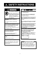
SAFETY INSTRUCTIONS WARNING CAUTION Do not open the equipment. Do not use the equipment for other than its intended purpose. Hazardous voltage which can cause electrical shock, burn or serious injury exists inside the equipment. Only qualified personnel should work inside the equipment. Use of the equipment as a stepping stool, for example, can result in personal injury or equipment damage. No one navigation device should ever be solely replied upon for the navigation of a vessel.
TABLE OF CONTENTS FOREWORD ....................................... iv SYSTEM CONFIGURATION ....... v 4. TRACK 4.1 Displaying Track .............................. 4.2 Stopping/Restarting Plotting of Track ................................................ 4.3 Changing Track Color ...................... 4.4 Track Plotting Method, Interval ........ 4.5 Changing Track Memory Capacity .. 4.6 Erasing All Track .............................. 1. OPERATIONAL OVERVIEW 1.1 1.2 1.3 1.4 1.5 1.6 1.7 1.
9. PLOTTER ALARMS APPENDIX 9.1 9.2 9.3 9.4 9.5 9.6 9.7 9.8 Menu Tree ................................................ A-1 Loran C Chains ........................................ A-4 Decca Chains ........................................... A-5 World Time ............................................... A-6 Geodetic Chart List .................................. A-7 Introduction ...................................... 9-1 Audio Alarm On/Off .......................... 9-1 Arrival Alarm .......................
FOREWORD A Word to GP-1650DF/1650F Owners Features The GP-1650DF is a totally integrated DGPS beacon receiver, GPS receiver, color video plotter and color video sounder. The GP1650F mostly shares the same features with the GP-1650DF except it does not have a DGPS beacon receiver. Congratulations on your choice of the FURUNO GP-1650DF COLOR DGPS/ PLOTTER/SOUNDER, GP-1650F COLOR GPS/PLOTTER/SOUNDER. We are confident you will see why the FURUNO name has become synonymous with quality and reliability.
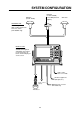
SYSTEM CONFIGURATION GPA-018 (for GP-1650DF) GPA-017 (for GP-1650F) 1.2 m Whip antenna (Option) GPA-019 ANTENNA UNIT Receives signal from GPS satellite and beacon reference station (GP-1650DF only). DISPLAY UNIT Ship’s position is calculated in longitude and latitude from signal received from the antenna unit and displayed on the screen. Ship’s mains 10.8—31.2 VDC External equipment (Autopilot, etc.) Temp.
This page is intentionally left blank.
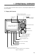
1. OPERATIONAL OVERVIEW This chapter acquaints you with the basics of your unit - from turning on the power to the soft key menu operation. 1.1 Display Unit Controls • Registers own ship's positions. • Marks man overboard position, event position. Cursor pad • Shifts cursor and display. • Selects items on menus. Registers items on menus. SAVE MOB ENTER Soft key's functions change depending on the display.
1.2 Inserting Mini Chart Card Insert appropriate mini chart card before turning on the power. 1. Push down the lid catch to open the mini chart card slot cover. The GP-1650DF/1650F takes about 90 seconds to find its position when turned on for the very first time. This is because the equipment has no satellite data, called the Almanac, in its database.
1.4 Adjusting Tone and Brilliance NORTH UP ZOOM IN ZOOM OUT 1. Press the [POWER/BRILL] key with a touch-and-release action. The tone and brilliance setting menu appears. COURSE UP WP-002 FISH Functions BRIDGE NAV POS DGPS 3D [Plotter Display] TONE TONE TONE DATE: OCT 21 1998 POSITION BRILL BRILL BRILL TIME 23:59:59 TRIP:123nm LAT/LON 34° 56.789' N 135° 56.789' E LAT LON SPD 16.3 RETURN TD RNG 27.2 nm kt CSE ZOOM BRG 245.8° 245.
1.6 Sounder Displays 1.7 Three sounder displays are available: Normal, Dual-frequency display and Plotter/ Sounder display. You may select a sounder display with the [SNDR] key. Most operations are carried out through the menu. The menu is opened and closed with the [MENU] key. Menus may be selected with the five soft keys to the right of menus. Options are selected with the cursor pad. 0 NORTH UP Menu Operation, Soft Keys 1. Press the [MENU] key to display the main menu.
1.8 Demonstration Display The demonstration display provides simulated operation of this unit. On the plotter display, own ship tracks, at the speed selected, a figure eight course or any course you enter, starting from position entered. All controls are operative; you may set destination, enter waypoints, etc. Simulated sounder operation is also provided. 1. Press the [MENU] key, followed by the soft keys CONFIGURATION and SYSTEM MENU to open the system menu. 2.
This page is intentionally left blank.
2. VIDEO SOUNDER OPERATION 2.1 Principle of Operation The video sounder determines the distance between its transducer and underwater objects such as fish, lake bottom or seabed and displays the results on screen. It does this by utilizing the fact that an ultrasonic wave transmitted through water travels at a nearly constant speed of 4800 feet (1500 meters) per second.
2.2 2. Press the soft key MODE/FREQ. The display changes as below. Sounder Display Description The figure below shows all indications and markers which may appear on the normal sounder display. MODE/FREQ 0 0.0 SELECT 50kHz ▲ ' AUTO CRUISING ™ AUTO FISHING ™ MANUAL SOUNDER 50 SELECT 200kHz ▼ Normal sounder display indications, markers 34° 12.345’ N 135° 12.345’ E Temp. scale Water temp. Graph Water temp.
Selecting sounder display mode Bottom-zoom display There are five display modes from which to choose: normal, marker zoom, bottom zoom, bottom lock and A-scope. To select a display, press the soft key SNDR FUNC on the normal sounder display to show the sounder function window, and press ▲ or ▼ to select the display. Press the soft key RETURN to close the window. This mode expands bottom and bottom fish echoes two to five times to vertical size of the screen, and is useful for determining bottom hardness.
4. Press ▲ or ▼ to select STD or WIDE. A-scope display This display shows echoes at each transmission with amplitudes and tone proportional to their intensities, on the right 1/3 of the screen. It is useful for estimating the kind of fish school and seabed composition. STD: The width of the sounder display is approx. 20 mm (Default setting). WIDE: The width is approx. 40 mm. 5. Press the [ENTER] key or the soft key ENTER. 0 68.
2.5 Automatic Sounder Operation Dual-frequency display: Press the soft key MODE. MODE/FREQ Automatic sounder operation is useful when you are preoccupied with other tasks and do not have time to adjust the display. ▲ ' AUTO CRUISING ™ AUTO FISHING ™ MANUAL ▼ How the automatic sounder works Figure 2-14 Mode/frequency window The automatic sounder function automatically selects the proper gain, range scale and clutter suppression level according to depth.
Selecting display range Range shifting Press the soft key RANGE to show the range window, and select range by the cursor. Press the soft key RETURN to finish. The basic range may be shifted up or down as desired. RANGE ▲ ' 15 ft ™ 30 ft ™ 60 ft ™ 120 ft ™ 200 ft ™ 400 ft ™ 1000 ft ™ 2500 ft ▼ Press the soft key SHIFT, and press ▲ or ▼ to shift the basic range. Press the soft key RETURN to finish.
2.8 Suppressing Interference Interference from other acoustic equipment operating nearby or other electronic equipment on your boat may show itself on the display as shown in Figure 2-20. To suppress interference, do the following: 1. Press the [MENU] key and the soft key SOUNDER SETUP OPTIONS. 2. Select NOISE LIMITER and press the soft key EDIT to show the noise limiter window. NOISE LIMITER ▲ 2.9 Suppressing Low Level Noise Light-blue dots may appear over most of screen.
2.10 Erasing Weak Echoes 2.11 White Marker Dirty water or reflections from plankton may be painted on the display in green or light blue. These weak echoes may be erased as follows: The white marker functions to display a particular echo color in white. For example, you may want to display the bottom echo (reddish-brown) in white to discriminate fish echoes near the bottom. Note that the bottom must be displayed in reddish-brown for the white marker to function. 1.
2.12 Selecting Picture Advance Speed 2.13 Selecting Background and Echo Colors The picture advance speed determines how quickly the vertical scan lines run across the screen. When selecting a picture advance speed, keep in mind that a fast advance speed will expand the size of the fish school horizontally on the screen and a slow advance speed will contract it. 1. Press the [MENU] key and the soft key SOUNDER SETUP OPTIONS. 2. Select HUE, and then press the soft key EDIT to show the hue window.
3. Select the menu item, and press the soft key EDIT. 2.14 Alarms Bottom alarm The bottom alarm sounds when the bottom echo is within the alarm range set. To activate the bottom alarm the depth must be displayed. Fish (B/L) alarm The bottom-lock fish alarm sounds when a fish echo is within a predetermined distance from the bottom. Fish (normal) alarm The normal fish alarm sounds when a fish echo is within the preset alarm range.
2.15 Interpreting the Display Bottom echo Zero line Echoes from the bottom are normally the strongest and are displayed in reddish-brown color but the color and width will vary with bottom composition, water depth, frequency, sensitivity, etc. The zero line (sometimes referred to as the transmission line) represents the transducer’s position, and moves off the screen when a deep phased range is used.
Surface noise/Aeration When the waters are rough or the boat passes over a wake, surface noise may appear near the zero line. As surface turbulence is acoustically equivalent to running into a brick wall, the bottom echo will be displayed intermittently. Similar noise sometimes appears when a water temperature difference (thermocline) exists. Different species of fish tend to prefer different temperature zones, so the thermocline may be useful to help identify target fish.
3. PLOTTER DISPLAYS 3.1 Course-up Presentation Modes The plotter display mainly shows chart, ship’s track, waypoints, and navigation data. Three types of display presentations are provided for the normal plotter display: north-up, course-up and auto course-up. To change the mode, use the presentation mode selection soft key, which is the 3rd soft key from the top. North-up Press the soft key COURSE UP to show the course-up display.
3.2 Cursor 3.4 Turning on the cursor, shifting the cursor Press the cursor pad to turn the cursor on, and the cursor appears at the own ship’s position. Operate the cursor pad to shift the cursor. The cursor moves in the direction of the arrow or diagonal pressed on the cursor pad. Cursor state determines what data is shown on the display. Cursor position is displayed in latitude and longitude or Loran or Decca TDs (depending on menu setting) at the top of the plotter display when the cursor is on.
Indices and chart enlargement Chart symbols When the soft key ZOOM OUT is used, you will see several frames appear on the chart. These frames are called indices and they show you what parts of the chart can be enlarged in the current picture range. The areas circumscribed with smaller frames can be enlarged, but the area enclosed by the largest frame cannot. FURUNO mini chart card The table below shows FURUNO mini chart symbols and their meanings.
Table 3-3 Comparison of FURUNO and Nav-Charts™ chart cards Item FURUNO Dot scrolling capability YES Course-up display YES Nav-Charts™ Range and bearing from own ship YES YES Lighthouse data YES *3 presentation YES Zoom at cursor position YES *1 0.125, 0.5, 1, 2... 2048 nm Same as left Chart offset data entry YES NO Centering YES *2 Range at Equator Example of data displayed Period (ex.: 6 seconds) Visibility in nautical mile (ex.: 12 miles) NAVAID: /FL 6S 12M FROM OS 52.38nm 48.
Enlarging an indication Emergency medical service Fueling station Water supply station Traveler’s service station An indication on the screen may be enlarged as follows: 1. Use the cursor pad to select the indication which you wish to enlarge. Selected indication is circumscribed with a red cursor. 2. Press the soft key ZOOM. To return to the normal nav data display, press the soft key RETURN.
Beacon information display 3.7 Equipped with a DGPS beacon receiver, your unit can show DGPS reference station information. Press the soft key BEACON INFO to show the DGPS reference station information. The steering display provides steering information such as range, bearing, ETA to destination, course and speed. DGPS reference station information Receive data status Beacon receiver setting status MODE FREQ BAUD RATE AUTO SEARCH 288.
How to read the XTE scale 3.8 The black boat-shaped mark shows own boat’s movement and direction, and amount to steer to return to course. Using Figure 313 as an example, you would steer right by 000.02 nautical miles to return to course. When this mark is out of range of the XTE scale, the mark color changes from black to yellow. The range of the XTE scale can be set as shown below (default: 0.5 nm). The highway display provides a graphic presentation of ship’s track along intended course.
3.9 Changing Operation Mode Operation mode can be changed between PLEASURE and FISHING. FISHING mode provides mark/line entry on the PLOTTER display. The mark can be entered up to 5000 points together with tracks. The apportion between track and mark memory can be changed at menu. Pressing the [HIDE/ SHOW] key changes the function of soft keys. Holding track, changing track color,and selecting color and form of mark/line can be performed by the soft keys directly. 3.
4. TRACK 4.1 Displaying Track s DISPLAY 1. Press the [MENU] key to open the main menu. MENU TRACK ON TRACK COLOR WHITE PLOT TIME TIME INTERVAL 01m00s DIST INTERVAL 00.10 nm TRACK MEMORY 2000 POINTS (MARK MEMORY) (3000) POINTS TRACK STATUS CHART SETUP OPTIONS TRACKING TRACK : 1000 / 2000 PTS used MARK : 5 / 3000 PTS used DISPLAY OPTIONS TRACK CONTROL EDIT STOP TRACK ERASE TRACK ERASE MARK RETURN GPS/DGPS/TD OPTIONS SOUNDER SETUP OPTIONS DGPS 3D DGPS 3D Figure 4-3 Track control menu 4.
4.2 Stopping/Restarting Plotting of Track TRACK COLOR ▲ ' RED ™ YELLOW ™ GREEN ™ LIGHT BLUE ™ PURPLE ™ BLUE ™ WHITE ▼ When your boat is at anchor or returning to port you probably won’t need to record its track. You can stop recording the track, to conserve the track memory, as follows: 1. Press the [MENU] key followed by the soft keys CHART SETUP OPTIONS and TRACK CONTROL. 2. Press the soft key STOP TRACK. The indication “TRACKING” in the TRACK STATUS window changes to “NOT TRACKING”.
PLOT ▲ ' TIME ™ DISTANCE ▼ Figure 4-5 Plot window 4. Press ▲ or ▼ to select TIME or DISTANCE. Distance is useful for conserving track memory, since no track is recorded when the boat is stationary. 4.5 Changing Track Memory Capacity The equipment stores a total of 5000 points of track and marks. This total may be freely apportioned as desired. The default setting is 2000 points of track and 3000 marks. You can change the memory capacity for track and marks.
4.6 Erasing All Track You can erase all track. Be absolutely sure you want to erase all track; erased track cannot be restored. 1. Press the [MENU] key followed by the soft keys CHART SETUP OPTIONS and TRACK CONTROL. 2. Press the soft key ERASE TRACK. You are asked if you sure to erase all track. 3. Press the [ENTER] key to erase, or press the [CLEAR] key to escape.
5. MARK The mark can be entered up to 5000 points together with tracks. The apportion between track and mark memory can be changed at menu. In the FISHING mode, pressing the [HIDE/ SHOW] key changes the function of the soft keys as follows. Plotter display 5.1 Entering Marks 34° 12.345’ N 135° 12.345’ E Select the fishing mode to enable entry of marks on the PLOTTER display. Select the location desired with the cursor, or turn off the cursor to enter the mark at own ship position.
5.2 Video sounder display 34° 12.345’ N 135° 12.345’ E CSE 245.8° SPD 16.3kt You can select shape, line and color of mark/ line on the TRACK display. SOUNDER 1. Press the [HIDE/SHOW] key to show the soft key MARK EIDT. RANGE 15.0 30 20 20 30 GAIN 2. Press the soft key MARK EDIT to show the MARK/LINE window. SHIFT 10 0 40 MODE/ FREQ 50 54.0 DGPS 3D MARK SHAPE SNDR FUNC 50k Press the [HIDE/SHOW] key. 34° 12.345’ N 135° 12.345’ E CSE 245.8° SPD 16.3kt Changing Mark Attributes .
Mark color 5.3 Press the soft key MARK COLOR to display the MARK COLOR window. Press ▲ or ▼ to select mark color desired. Mark size can be selected from STD (standard) and SMALL. MARK COLOR ▲ ' RED ™ YELLOW ™ GREEN ™ LIGHT BLUE ™ PURPLE ™ BLUE ™ WHITE ▼ Figure 5-6 MARK COLOR window 4. Press the soft key ENTER or the [ENTER] key. 5. Press the soft key RETURN to finish. Marks/lines entered hereafter are inscribed in the shape, color and line type selected here. Changing Mark Size 1.
5.4 Erasing Marks Erasing individual marks/lines 1. Operate the cursor pad to place the cursor on the mark you want to erase. 2. Press the [CLEAR] key. The mark selected is erased. Note: To erase line, place the cursor on an edge of the line. The line segment will be erased. Erasing whole marks/lines You can erase all marks and lines. Be absolutely sure you want to erase all marks and lines; erased marks and lines cannot be restored. 1.
6. WAYPOINTS 6.1 Entering Waypoints In navigation terminology, a waypoint is a particular location on a voyage whether it be a starting, intermediate or destination point. A waypoint is the simplest piece of information your equipment requires to get you to a destination, in the shortest distance possible. This unit has 835 waypoints (including quick waypoints) into which you can enter position information.
ADD/EDIT/MOVE WAYPOINTS WPT Changing the shape and color of waypoint mark LOCAL LIST 1. Press the soft key SELECT MARK. ALPHA/NUMERIC LIST 2. Press the soft key MARK SHAPE to open the mark shape selection window. WAYPOINT BY CURSOR WAYPOINT BY RANGE & BEARING MARK SHAPE RETURN DGPS 3D Figure 6-4 waypoint menu 3. Press the soft key WAYPOINT BY CURSOR. The plotter display appears. 4. Operate the cursor pad to place the cursor on the location desired. 5. Press the soft key NEW WPT.
Changing waypoint name, comment, proximity alarm radius 34° 12.345’ N 135° 12.345’ E FROM ’X’ 0.01nm 224.1 WPT RNG BRG ZOOM IN 1. If necessary, you can change the name (1 to 6 characters), comment (13 characters), L/L position and the proximity alarm radius (explained in detail in Chapter 8) as follows: a) Select the NAME, COMMENT or PROXIMITY ALARM RADIUS field. b) Use the cursor pad to select character or digit. c) Enter appropriate data with the alphanumeric keys.
BRG. 23.8° 1.75nm FISH01 RNG. 33°12.345' N ABCDEFGHIJKL WPT LOCAL 135°23.456' W GO TO WPT001 12:30 29SE97 BRG. 90.0° RNG. 2.51nm 33°23.456' N 135°23.567' W BRG. 180.0° 5.07nm ABCDEF RNG. 34°12.345' N 15:21 01OCT97 135°54.321' W BRIDGE BRG. 359.9° RNG. 8.01nm 34°12.345' N 135°54.321' W 16:45 01OCT97 DGPS 3D NEW WPT EDIT WPT BRG. 180.0° 5.07nm ABCDEF RNG. 34°12.345’ N 15:21 01OCT97 135°54.321’ W BRIDGE BRG. 359.9° RNG. 8.01nm 34°12.345’ N 135°54.
6.4 Waypoint Mark Size You may change the size of all waypoint marks to small or large (default), or turn them off. 3. Operate the cursor pad to place the cursor on the waypoint which you want to change. A flashing diamond mark appears on the waypoint when it is correctly selected. 1. Press the [MENU] key to open the main menu. 4. Press the soft key EDIT/MOVE. 2. Press the soft key CHART SETUP OPTIONS. 6. Operate the cursor pad to place the cursor on the location desired. 3.
This page is intentionally left blank.
7. ROUTES Often a trip from one place to another involves several course changes, requiring a series of route points (waypoints) which you navigate to, one after another. The sequence of waypoints leading to the ultimate destination is called a route. Your unit can automatically advance to the next waypoint on a route, so you do not have to change the destination waypoint repeatedly. You can store up to 200 routes. A route may consist of 35 points.
Entering routes by the cursor CONNECT ROUTE This method allows you to construct a route directly on the plotter display, using existing waypoints or new locations. Any new location will be saved as a waypoint, under the next consecutive waypoint number. FIRST SECOND ______ ______ FORWARD REVERSE NEW ROUTE F<-->R SAVE 1. Follow step 1-4 in “Entering routes through the route list.” 2. Press the soft key PLOT. The plotter display appears. DGPS 3D CANCEL Figure 7-3 Connect route window 3.
EDIT ROUTE ROUTE NAME: ABCDEF COMMENT: ABCDEFGHIJKL 01 s WPT001 02 WPT002 03 WPT003 04 WPT004 05 WPT005 34°12.345’N 135°54.321’W 34°23.456’N 136°10.255’W 35°11.222’N 136°55.889’W 35°22.878’N 136°44.333’W 34°15.279’N 135°34.111’W LEG 204.8° 33.83nm 22.0° 34.27nm 35.1° 2.89nm 125.6° 31.25nm INSERT WPT REMOVE WPT CHANGE WPT COORD TYPE RETURN RETURN DGPS 3D 5. Press ▲ or ▼ to place the cursor at the location where you want to insert a waypoint. 6.
Removing route waypoints from the plotter display Next consecutive route number 1. Press the [WPT/RTE] key followed by the soft key ROUTES to open the route menu. ROUTE NAME SAVE ROUTE START LOG 006 2. Press ▲ or ▼ to select the route desired. COMMENT 3. Press the soft key EDIT ROUTE. 4. Press the soft key PLOT to show the plot screen. 5. Operate the cursor pad to place the cursor on the waypoint you want to remove from the route. 6. Press the soft key REMOVE WPT. 7.
NORTH UP ZOOM IN ZOOM OUT COURSE UP DGPS 3D SA VE NAV L/L SAVE icon Figure 7-8 SAVE icon appearance on the plotter display 7. Press the [SAVE/MOB] key with a touchand-release action to enter a waypoint mark at own ship position. A new waypoint is created under the next consecutive waypoint number and that waypoint is added to the route. 8. Repeat step 7 as necessary. 35 waypoints can be entered. 9. Press the [WPT/RTE] key followed by the soft key CREATE VOYAGE BASED ROUTE. 10.
This page is intentionally left blank.
8. NAVIGATION 8.1 Navigating to “Quick Points” The “quick point” feature allows you to navigate to point(s) without retaining the data indefinitely in your unit’s memory. Each time a quick point is entered the previous quick points having the same quick point numbers are written over. Selecting quick point entry method You need to tell your unit how to set the quick point: 1 POINT, 35 POINT (up to 35 points) or WPT/PORT SERV. (For WPT/PORT SERV, see the next page.) 3.
8.2 Navigating to Waypoints (waypoint list) 1. Press the [WPT/RTE] key to open the waypoint & route menu. + 40°45.971’N 13°57.462’E 4. Select a waypoint. 5. Press the soft key GO TO. The plotter display appears. A light-blue line runs between destination selected and own ship’s position. Arrows on the line show the direction to the follow. Waypoint data appear at the top of screen. 0.26 nm 180.2° GO TO QUICK ROUTE NEAR SRVICE PUNTA CORNACCHIA PORT ACCO AMENO 2.
8. If you selected PORT in step 7, use the cursor pad to select a port and press the [ENTER] key. Make a route using the soft keys and press the [ENTER] key. (If you want to go directly to that port, simply press the soft key ADD QP followed by the [ENTER] key.) FISH WPT FROM OS 1.3 nm 208.5° ZOOM IN ZOOM OUT WP-002 GO TO WPT FISH If you selected NEAR SERVICE in step 7, select service mark desired and then press the soft key ENTER. Then, the display shows the locations of those services nearest you.
Restarting navigation Setting speed for ETA calculation When you steer to avoid an obstacle or the vessel drifts, you may go off your intended course (Line 1 in Figure 8-7). Use the steering or highway display to return to course. Speed, which may be input manually or automatically, is required to calculate ETA (Estimated Time of Arrival) to a waypoint.
To select waypoint switching method do the following: 1. Press the [MENU] key. 2. Press the soft key DISPLAY OPTIONS. 3. Select WAYPOINTS SW. 4. Press the soft key EDIT to show the waypoint sw window. 5. Select appropriate waypoint switching method. 6. Press the soft key ENTER to close the window. 8.5 Cancelling Navigation 1. Press the [WPT/RTE] key. 2. Press the soft key LOG. 3. Press the soft key STOP. 4. Press the [ENTER] key to go stand by. 5. Press the soft key RELEASE. 6. Press the [ENTER] key.
This page is intentionally left blank.
9. PLOTTER ALARMS 9.1 4. Press ▲ or ▼ to select ON or OFF. Introduction There are five plotter-related alarms which generate both audible and visual alarms: Arrival alarm, Anchor Watch alarm, XTE (Cross Track Error) alarm, Proximity alarm, and Speed alarm. When an alarm setting is violated the buzzer sounds, and the speaker icon ( ) appears in red. You may silence the alarm by pressing the [CLEAR] key. The icon remains on the screen until the cause of the alarm is removed or the alarm is deactivated. 9.
9.4 Anchor Watch Alarm The anchor watch alarm informs you that your boat is moving when it should be at rest. When the anchor watch is active, a red dashed circle marks the anchor watch area. 9.5 XTE (Cross Track Error) Alarm The XTE alarm warns you when your boat is off its intended course. When the XTE alarm is active two red dashed lines mark the XTE alarm area. Alarm setting Your ship’s position where you start the anchor watch alarm.
9.6 Speed Alarm The speed alarm warns when your boat’s speed is within, over/under or under the speed range set. 1. Press the [ALARM] key to open the alarm menu. 2. Press ▲ or ▼ to select SPEED ALARM. 3. Press the soft key EDIT to display the speed alarm window. SPEED ALARM ▲ ' WITHIN 15.0 ~ 15.3 kt ™ OVER/UNDER ™ OFF ▼ 9.7 Proximity Alarm The proximity alarm alerts you when your vessels nears a waypoint by the distance set for that waypoint on the waypoint list.
9.8 Alarm messages Alarm Information When an alarm setting has been violated the buzzer sounds and the speaker icon (shown in red) appears. You can see which alarm has been violated, as well as silence the buzzer, on the alarm menu display. ALARM ARRIVAL ALARM ANCHOR ALARM PROXMTY ALARM XTE ALARM SPEED ALARM ON ON 0.100nm ON 0.050nm ON ON 0.100nm OVER/UNDER 12.5 ~ 15.0kt ALARM INFORMATION ALARM1 EDIT CLEAR ALARM NEXT PAGE Alarm information (Example: Arrival alarm) Figure 9-11 Alarm menu 2.
10. SAVING AND LOADING DATA TO/FROM MEMORY CARD The following data can be saved to memory card: 10.2 Saving Data to Memory Card • Mark/line • Waypoints/routes • Track • Configration (menu settings) The memory card can save four items of data; track, mark/line, waypoint/route and configuration. 10.1 Formatting Memory Cards Before you can use a memory card it must be formatted. Note that formatting a used card erases all saved data. 1. Insert the memory card you want to format into the slot. 2.
Error message Memory card not inserted Press the [ENTER] key to return to the SAVE DATA display. MEMORY CARD NOT INSERTED. INSERT CARD PRESS "ENTER" key TO CONTINUE. Fiugre 10-3 NOT INSERTED message Unformatted memory card Press the [ENTER] key to return to the SAVE DATA display. And format it refering to the previous page. MEMORY CARD NOT FORMATTED PRESS "ENTER" key TO CONTINUE. Figure 10-4 NOT FORMATTED message Wrong card inserted Appears when a chart card is inserted.
6. After you select all items desired, press the soft key LOAD DATA to load data. The following message appears. NOW LOADING DATA FROM MEMORY CARD. DO NOT TURN OFF THE POWER UNTIL LOADING COMPLETE. Figure 10-8 LOAD DATA message After loading is completed, the following message appears. COMPLETE LOADING DATA. PRESS "ENTER" KEY TO CONTINUE. Figure 10-9 COMPLETE message 7. Press the [ENTER] key.
This page is intentionally left blank.
11. CUSTOMIZING YOUR UNIT This section describes the various options which allow you to set up your unit to suit your needs. 11.1 CHART SETUP OPTIONS menu The chart offset options menu provides three menus: chart offset, track control, and chart details. 1. Press the [MENU] key to open the main menu. CHART OFFSET menu In some instances position may be off by a few minutes. For example, the position of the ship is shown to be at sea while it is in fact moored at a pier.
CHART DETAILS menu 1. Press the [MENU] key followed by the soft keys CHART SETUP OPTIONS and CHART DETAILS. sLAT/LON GRID TEXT INFO WAYPOINT WAYPOINT NAME INDEX LANDMASS BACKGROUND NAV AIDS SECTOR INFO OTHER SYMBOLS GREEN ON LARGE ON ON BRT YELLOW BLUE ON OFF WHITE DGPS 3D CHART DETAIL EDIT DEPTH INFO RETURN Figure 11-3 Chart details menu BACKGROUND: Select background color to black or blue (default setting). NAV AIDS: Turns aids to navigation symbols (for example, buoys) on/off.
Display setup1 menu description BEARING RNG & BRG MODE A navigation device outputs both true and magnetic bearings. A magnetic bearing is true bearing plus (or minus) earth’s magnetic deviation. Thus the equation for finding magnetic bearing is; The GPS receiver calculates the range, bearing, cross track error (XTE) and ETA to TO waypoint when you set a destination.
POSITION DISPLAY TEMP SOURCE Displays position in latitude and longitude (default setting) or Loran C or Decca TDs. Selects source of water temperature input; NMEA (external), or OWN XDCR (water temperature sensor, default setting). SET GO TO METHOD TEMP GRAPH Selects the method for entering the quick point: 1 POINT (default setting), 35 POINT (2-35 points), or WPT/PORT SER. For further details see pages 8-1 and 8-2. Displays water temperature in line graph form. (See Figure 2-2 on page 2-2.
11.3 GPS/DGPS/TD OPTIONS menu This menu sets up GPS and DPGS receivers and enables display of position in Loran C or Decca TDs. 1. Press the [MENU] key. 2. Press the soft key GPS/DGPS/TD OPTIONS to display the GPS/DGPS/TD options menu. GPS/DGP OPTION GPS SETUP OPTIONS DGPS SETUP OPTIONS TD SETUP GEODETIC DATUM Your equipment is preprogrammed with most of the major chart systems of the world. Although the WGS-84 system, the GPS standard, is now widely used other categories of charts still exist.
SPD/CSE SMOOTHING LATITUDE, LONGITUDE During position fixing, ship’s velocity (speed and course) is directly measured by receiving GPS satellite signals. The raw velocity data may change randomly depending on receiving conditions and other factors. You can reduce this random variation by increasing the smoothing. Like with latitude and longitude smoothing, the higher the speed and course smoothing the more smoothed the raw data.
DGPS MODE Displaying LORAN C TDs Select ON to use the DGPS mode. The default setting is ON. A DGPS beacon receiver must be connected to use this mode. 1. Select GRI and press the soft key EDIT to show the GRI & sta. pair window. BEACON FREQUENCY DGPS reference station can be searched automatically or manually. For manual search, select MANUAL here, and use the cursor pad to select frequency of DGPS reference station. The default setting is AUTO.
4. If necessary, you may enter position offset to refine Decca position. Select DECCA CORRECTION1 or CORRECTION2 and press the soft key EDIT. Enter correction value and press the soft key ENTER or the [ENTER] key. Use the soft key + <--> - to switch from plus to minus and vice versa. WHITE MARKER 11.4 SOUNDER SETUP OPTIONS menu SIGNAL LEVEL Displays selected echo color in white. For further details see page 2-8. HUE Select echo color and background color. See page 2-9 for further details.
4. Select a range, ZOOM RANGE or B/L RANGE, and press the soft key EDIT. ZOOM RANGE selects the range to zoom in the marker and bottom zoom modes. The setting range is 7 to 5000 feet, and the default setting is 30 feet. B/L RANGE sets the expansion width for the bottomlock display, 10 or 20 feet. The default setting is 20 feet. TVG 200kHz, TVG 50kHz: TVG (Time Varied Gain) compensates for propagation attenuation of the ultrasonic waves.
11.5 CONFIGURATION menu FORMAT The configuration menu has facilities for setting up data ports, uploading/downloading data, self test, demonstration mode setup, and memory clearing. Selects NMEA0183 version 1.5 or 2.0. If you are unsure of the version of external equipment try both and choose the one which outputs data correctly. The default setting is version 2.0. 1. Press the [MENU] key. 2. Press the soft key CONFIGURATION to display the configuration menu.
UPLOAD/DOWNLOAD DATA menu This menu allows you to upload waypoint and route data to a PC or download the same data from a PC, via the DGPS connector at the back of display unit. The menu can be displayed by pressing the [MENU] key followed by the soft keys CONFIGURATION and UPLOAD/DOWNLOAD DATA. For detailed information, see the Installation Manual. For memory card, see chapter 10.
GP-1650DF/1650F DGPS 1 2 3 4 5 6 7 NC NC RD (YELLOW) NC SD (RED) SG (BLUE) SHIELD PC/AT DSUB 25-pin (EIA-232) PC/AT DSUB 9-pin (EIA-574) 3 (TxD) 2 (TxD) 2 5 4 6 7 8 3 (RxD) 7 (GND) 4 (DTR) 5 (DSR) 6 (RTS) 20 (CTS) (RxD) (GND) (DTR) (DSR) (RTS) (CTS) Figure 11-22 Connection of GP-1650DF/GP-1650F to PC Waypoint data format P F E C , G P w p l, llll.llll, a , y y y y y .
Note 2: A route can may contain 35 waypoints and GPRTE sentence for one route data may exceed 80 byte limitation. In this case, route data is divided into several GPRTE sentences (Max. 4 sentences). This value shows the number of sentences the route data has been divided. SYSTEM menu This menu provides testing facilities, demonstration mode setup and memory/trip clear. You may display it by pressing the [MENU] key followed by the soft keys CONFIGURATION and SYSTEM MENU.
This page is intentionally left blank.
12. USING C-MAP NT MODEL The GP-1650DF/1650F C-MAP NT series uses FURUNO mini chart card and C-MAP NT-FP chart card. These charts show accurate coastlines, depth contours, place names, aids to navigation such as buoys and lighthouses, and other navigational marks. 12.1 Inserting Chart Card 12.2 Cursor and Data Display Besides its fundamental functions of providing position data, the cursor can also show caution area, depth area, source of data, etc.
4. Press ! or " to select the item desired. Objects 5. Press the soft key ENTER or the [ENTER] key to display details for object selected Objects. Navigation mark, fixed Extended navigational aid, ge Light Light Light Light Depth contour Land area Source of data Caution area Information LEUCTEUE DIE ATE ENTAEL T NU DIE LAGEN DE ICTIGEN EUE. LIGTS ONL TE PINC IPAL LIGTS AE SON ON TIS CAT. MISSEISUNG SIEE ATEN GOESSEEN MASSSTAS. M AGNETIC AIATION LOCAL MAGNE TIC ANOMALIES SEE LAGE SCAL E CATS.
2. Press the [ENTER] key to open the Objects window. 7. Press the soft key ENTER or the [ENTER] key to show the tidal graph for entered date. 8. Press # or $ to locate the vertical cursor on the time desired. Time and height are shown to the left of the graph. 9. Press ! or " to shift the level cursor. Draught is shown to the left of the graph. Objects Tide height Depth contour Caution area Depth area Source of data 10. Press the soft key CANCEL to close the TIDE window.
6. Press the soft key GO TO. Soft key titles change as in Figure 12-10. If GO TO key is not displayed, press the cursor pad. + 40˚45.971'N 13˚57.462'E FROM OS 0.26 nm 180.2˚ + 40˚45.971'N 13˚57.462'E FROM OS 0.26 nm 180.2˚ GO TO GO TO PUNTA CORNACCHIA ACCO AMENO QUICK ROUTE NEAR SRVICE CASAMICCIOLA PUNTA CORNACCHIA ACCO AMENO ENTER ISCHIA PORTO DGPS 3D I.SELECT ISCHIA ICON BY KEY. CANCEL GO TO ISCHIA PORTO Figure 12-15 Sample filling station locations CASAMICCIOLA I.
d) Press the [ENTER] key to finish. A line connects between own ship and the port service. And the range and bearing from own ship to first waypoint appears. Note: Destination is automatically cancelled if there is no port for service selected. 12.5 Setting Chart Setup Options CHART DETAILS menu 1. Press the [MENU] key followed by the soft keys CHART SETUP OPTIONS and CHART DETAILS.
DEPTH INFO soft key: Turns the DEPTH INFO display on/off and sets it color in FURUNO chart, or selects the depth areas limit and spot sounding & bathymetric range in C-MAP NT-FP chart. 1. While displaying chart details menu, press the soft key DEPTH INFO to show the following display. DEPTH INFO FOR FURUNO CHART DEPTH DEPTH DEPTH DEPTH < 10 m = 10 m > 10 m INFO RED YELLOW LIGHT BLUE RED EDIT Note 1: Depth data depends on the registered value at "depth area". (See page 1.
12.7 Displaying Program Number 1. Press the [MENU] key to open the main menu. 2. Press the soft key CONFIGURATION to show the configuration menu. 3. Press the soft key SYSTEM MENU to open the system menu. 4. Press the soft key SELF TEST to open the test menu. 5. Press the soft key MEMORY, I/O TEST to start the test. Test results and program numbers are shown as below. Program Number TEST PROGRAM: OK No.14518160** SRAM: OK INTERNAL BATTERY: OK GPS RECEIVER: OK No.
This page is intentionally left blank.
13. MAINTENANCE & TROUBLESHOOTING 13.1 Maintenance Regular maintenance is essential for good performance. A maintenance program should be established and should at least include the items listed in Table 13-1. WARNING Do not open the equipment. Hazardous voltage which can cause electrical shock, burn or serious injury exists inside the equipment. Only qualified personnel should work inside the equipment.
13.2 Replacement of Fuse, Battery The fuse on the power cable protects the system from reverse polarity of the ship’s mains and equipment fault. If the fuse blows, find the cause before replacing it. Use only a 3A fuse. Using the wrong fuse will damage the unit and void the warranty. A battery installed on a circuit board inside display unit preserves data when the power is turned off. The life of the battery is about three years. When the battery voltage is low the battery icon ( ) appears on the display.
Table 13-3 Simple troubleshooting (sounder) If... no picture but marks and characters appear Then... check if picture advance speed is set to "STOP" on the sounder setup options menu. check for loosened transducer connector. picture appears but no zero line If using manual video sounder operation, range is shifted; set shifting to zero to correct. picture sensitivity is too low check gain setting, if using manual operation. marine life or air bubbles may be clinging to transducer face.
4. Press the soft key SELF TEST to open the test menu. 13.5 Diagnostic Tests Memory, I/O port test TEST This test conducts a general check of the display unit and the antenna unit. The unit displays the results for each device or component checked as OK or NG (No Good). MEMORY•I/O TEST KEYBOARD TEST 1. Press the [MENU] key to open the main menu. 2. Press the soft key CONFIGURATION to show the configuration menu.
Keyboard test Display test This test checks all controls for proper operation. 1. Press the [MENU] key followed by the soft keys CONFIGURATION, SYSTEM MENU and SELF TEST to display the self test menu. 1. Press the [MENU] followed by the soft keys CONFIGURATION, SYSTEM MENU and SELF TEST to display the self test menu. 2. Press the soft key KEYBOARD TEST to display the screen for testing the keyboard. 2. Press the soft key TEST PATTERN to open the test pattern display. 3.
13.6 Clearing Memories The memory, which stores marks, tracks and initial settings, can be cleared to start afresh. When this done all default settings are restored. 1. Press the [MENU] key followed by the soft keys CONFIGURATION and SYSTEM MENU. 2. Press the soft key MEMORY/TRIP CLEAR to open the clear memory menu. CLEAR MEMORY s CLEAR PLOTTER MEMORY NO CLEAR GPS MEMORY NO CLEAR ALL MEMORY NO TRIP METER RESET NO DGPS 3D EDIT RETURN Figure 13-7 Clear memory menu 3.
MENU TREE MENU key Default settings shown in bold italic. CHART SETUP OPTIONS CHART OFFSET TRACK CONTROL Default settings shown in bold italic.
1 SOUNDER SETUP OPTIONS NOISE LIMITER (OFF, NL1, NL2, NL3) CLUTTER (AUTO, 0-9) WHITE MARKER [0-16 (or 0-8), Default: 0] HUE (1-9, Default: 1) SIGNAL LEVEL [SL1, SL2, SL3, SL4, SL5, SL6 (or SL1, SL2, SL3), Default: OFF] PICTURE ADVANCE (2/1, 1/1, 1/2, 1/4, 1/8, STOP) E/S WINDOW (STD, WIDE) : When 8 is selected in HUE window Soft key SYSTEM SETUP FISH ALM LVL (HIGH, NORMAL, LOW) TX POWER (ON, OFF) TVG 200 kHz (0-9, Default: 5) TVG 50 kHz (0-9, Default: 5) ECHO OFFSET 200 kHz (-20 - +20, Default: 0) ECHO OF
WPT/RTE key WAYPOINTS LOCAL LIST ALPHA/NUMERIC LIST WAYPOINT BY CURSOR WAYPOINT BY RANGE & BEARING ROUTES LOG CREATE VOYAGE BASED ROUTE ALARM key Page 1 AUDIO ALARM (ON, OFF) ARRIVAL ALARM (ON, OFF) ANCHOR ALARM (ON, OFF) PROXIMITY ALARM (ON, OFF) XTE ALARM (ON, OFF) SPEED ALARM (WITHIN, OVER/UNDER, OFF) Page 2 (By soft key NEXT PAGE) BOTTOM ALARM (ON, OFF) FISH (B/L) ALARM (ON, OFF) FISH (NORMAL) (ON, OFF) TEMP.
Loran C Chains Chain GRI S1 S2 S3 S4 S5 Central Pacific 4990 11 29 – – – Canadian East Coast 5930 11 25 38 – – Commando Lion (Korea) 5970 11 31 42 – – Canadian West Coast 5990 11 27 41 – – South Saudi Arabia 7170 11 26 39 52 – Labrador Sea 7930 11 26 – – – Eastern Russia 7950 11 30 46 61 – Gulf of Alaska 7960 11 26 44 – – Norwegian Sea 7970 11 26 46 60 – Southeast USA 7980 11 23 43 59 – Mediterranean Sea 7990 11 29 47 – – We
Decca Chains Chain No. Chain Chain code Location Chain no.
World Time A-6
Geodetic Chart List 001: 002: 003: 004: 005: 006: 007: 008: 009: 010: 011 012: 013: 014: 015: 016: 017: 018: 019: 020: 021: 022: 023: 024: 025: 026: 027: 028: 029: 030: 031: 032: 033: 034: 035: 036: 037: 038: 039: 040: 041: 042: 043: 044: 045: 046: 047: 048: 049: 050: 051: 052 053: 054: 055: 056: 057: 058: 059: 060: 061: 062: 063: 064: 065: 066: 067: 068: 069: 070: 071: 072: 073: 074: 075: 076: 077: 078: 079: 080: 081: 082: 083: 084: 085: 086: 087: 088: 089: 090: 091: 092: 093: WGS84 WGS72 TOKYO NORTH AMER
SPECIFICATIONS OF COLOR GPS/ PLOTTER/ SOUNDER: GP-1650F COLOR DGPS/ PLOTTER/ SOUNDER: GP-1650DF 1. GENERAL (1) Display 5.6 inch high resolution color LCD (2) Projection Mercator (3) Usable Area 85° latitude or below (4) Display Mode Plotter, Plotter/Sounder, Sounder, Highway display, Waypoint display, XTE(Cross Track Error) display (5) Alarms Arrival and Anchor watch, Cross track error and border alarms, Ship’s speed in and out alarms, Water temperature, Fish school 2.
(3) Colors Red, yellow, green , purple, light-blue, blue, white (4) Memory Capacity Track/Mark: 5000 points, waypoint: 800 points, (5) Storage Capacity Simple route: 200 routes with 35 waypoints each (6) MOB 1 point (7) Quick routes 1 course (8) Electronic Chart FURUNO chart card or NAVIONICS chart card available C-MAP chart card also available for C-MAP NT Model 5.
INDEX A D A-scope display 2-4 Alarm information window 2-10, 9-4 ALARM key 2-10 Alarm messages 9-4 Alarms alarm information window 9-4 alarm message 9-4 anchor watch alarm 9-2 arrival alarm 9-1 audio alarm 9-1 bottom alarm 2-10 DGPS alarm 11-7 fish (B/L) alarm 2-10 fish (normal) alarm 2-10 proximity alarm 9-3 speed alarm 9-3 temperature (water) alarm 2-10 XTE alarm 9-2 Anchor watch alarm 9-2 Antenna height 11-6 Arrival alarm 9-1 Audio alarm 9-1 Auto course-up mode 3-1 Automatic sounder operation 2-5 Decc
H N Highway display 3-7 Hue (sounder) 2-9 Nav data display 3-5 Navigation cancelling 8-5 multiple quick points 8-1 ports, port service 8-2 quick points 8-1–8-5 restarting 8-4 route 8-3 route in reverse order 8-3 single quick point 8-1 specific route leg 8-3 switching route waypoints 8-4 waypoints 8-2 Noise limiter 2-7 North-up mode 3-1 I Indications enlargement of nav data 3-5 sounder display 2-2 Interference rejection 2-7 K Keyboard test 13-5 L Lat/lon display resolution 11-3 Lighthouse data 3-4 Loca
Routes connecting (two) 7-2 entering by cursor 7-2 entering through route list 7-1 entering track based 7-4 erasing 7-5 inserting waypoints on the plotter display 7-3 inserting waypoints through route list 7-2 navigating 8-3 navigating in reverse order 8-3 navigating specific leg 8-3 removing from plotter display 7-4 removing waypoints through route list 7-3 restarting navigation of 8-4 switching waypoints 8-4 S Track color 4-2 displaying 4-1 erasing all 4-4 plotting interval 4-2 stopping/restarting plott