INSTALLATION MANUAL COLOR DGPS/PLOTTER GP-1850D COLOR GPS PLOTTER GP-1850 Safety Instructions for the Installer ....................... i Equipment Lists ..................................................... ii System Configuration ........................................... iv 1. Installation of Standard Equipment ............... 1-1 1.1 Installation of Display Unit .............................................. 1-1 1.2 Installation of Antenna Unit ............................................. 1-3 2.
C Yo u r L o c a l A g e n t / D e a l e r 9-52, Ashihara-cho, Nishinomiya, Japan Te l e p h o n e : Te l e f a x : 0 7 9 8 - 6 5 - 2 111 0798-65-4200 All rights reserved. Printed in Japan PUB. No. IME-43952-G (TENI) GP-1850/1850D FIRST EDITION G : : FEB.
SAFETY INSTRUCTIONS Safety Instructions for the Installer CAUTION WARNING Do not work inside the equipment unless totally familiar with electrical circuits. Ground the equipment to prevent electrical shock and mutual interference. Confirm that the power supply voltage is compatible with the voltage rating of the equipment. Hazardous voltage which can shock, burn or cause serious injury exists inside the equipment. Connection to the wrong power supply can cause fire or equipment damage.
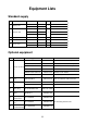
Equipment Lists Standard supply NO. Name Type Code No. GP-1850 1 2 Qty - Remarks for GP-1850 Display unit 1 Antenna Unit GP-1850D - for GP-1850D GPA-017 - for GP-1850 GPA-018 - GPA-019 - 1 for GP-1850D for GP-1850D 3 Spare parts SP14-02501 004-375-260 1 Fuse 4 Installation materials CP14-05200 000-041-496 1 Power cable, cable assy. FP14-02401 004-375-270 1 Hard cover 5 Accessories FP14-02403 004-376-180 1 Screws, rubber cushion Optional equipment NO.
Optional equipment (con't) NO. 9 10 11 Name Antenna Unit Rectifier Cable Assy. Type Code No.
System Configuration The GP-1850/1850D mainly consists of a display unit and a GPS antenna. A DGPS beacon receiver is provided inside the display unit for GP-1850D type. The mini chart card drive in the display unit loads electronic charts. External equipment which may be connected include an autopilot and a DGPS beacon receiver (GP1850). ANTENNA UNIT GPA-018 (GP-1850D) ANTENNA UNIT GPA-019 (GP-1850D) 1.
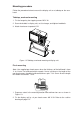
1. Installation of Standard Equipment 1.1 Installation of Display Unit Mounting considerations The display unit can be installed on a tabletop, on the overhead or flush mounted in a console or panel. Hard Cover Tabletop Overhead Figure 1-1 Tabletop, overhead mounting methods When selecting a mounting location for the display unit keep the following in mind: • Keep the display unit out of direct sunlight. • The temperature and humidity should be moderate and stable.
Mounting procedure Follow the procedure below to mount the display unit on a tabletop or the overhead. Tabletop, overhead mounting 1. Fix the hanger by four tapping screws M5 X 16. 2. Screw knob bolts in display unit, set it to hanger, and tighten knob bolts. 3. Attach hard cover to protect LCD. WA RN ING Figure 1-2 Tabletop, overhead mounting of display unit Flush mounting Note: Use supplied pan head screws when the thickness of the bulkhead is from 11 to 14 mm.
242 0.5 6-R2.25 50 244 1 143 1 4.5 89 0.5 147 0.5 Pan head screws 15 0.5 238 1 Flush mount (Cutout for flush mount) Figure 1-3 Flush mounting of display unit 1.2 Installation of Antenna Unit Mounting considerations Install the antenna unit referring to the installation diagram on page D-3 or D-4. When selecting a mounting location for the antenna unit, keep in mind the following points: • Select a location out of the radar beam.
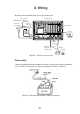
2. Wiring All wiring are terminated at the rear of the display unit. Antenna unit ANTENNA UNIT GPA-019 (GP-1850D) DISPLAY UNIT GPA-018 (GP-1850D) GPA-017 (GP-1850) Earth terminal Ground Ground ANT XDR TEMP/SPD DGPS NMEA + GND 1 3 2 12 - 24 VDC External equipment DGPS beacon receiver (option for GP-1850, Black RS-232C only) White Shield Figure 2-1 Display unit, rear view Power cable Connect the power cable to the power connector.
Antenna unit Connect the antenna cable to the ANT connector. Ground The display unit contains several CPUs. While they are operating, they radiate noise, which can interfere with radio equipment. Ground the unit to prevent Ground the equipment to interference. The grounding wire should prevent electrical shock be 1.25 sq or larger and as short as and mutual interference. possible. Connect the grounding wire to ship's ground.
How to attach the N-P-8DFB connector Outer Sheath Armor Dimensions in millimeters. Inner Sheath Shield 50 Remove outer sheath and armor by the dimensions shown left. Expose inner sheath and shield by the dimensions shown left. 30 Cover with heat-shrink tubing and heat. Cut off insulator and core by 10mm. 10 30 Twist shield end. Ship on clamp nut, gasket and clamp as shown left. Clamp Nut Gasket Clamp (reddish brown) Aluminum Foil Fold back shield over clamp and trim. Trim shield here.
3. Initial Settings 3.1 NMEA Setting NMEA port 1. Press the [MENU] key. 2. Press the software key labeled "CONFIGURATION". 3. Press the software key labeled "SETUP NMEA PORT1". 4. Select "FORMAT" by the arrow key. 5. Press the software key labeled "EDIT" to display the following message. s FORMAT OUTPUT FORMAT NMEA 0183 SETUP PORT 1 VER 1.5 ▲ NMEA0183 Ver1.5 ' NMEA0183 Ver2.0 ▼ ENTER CANCEL DGPS 3D Figure 3-1 Output Format display, NMEA port 6. Select NMEA version desired by the arrow key. 7.
DGPS port 1. Press the [MENU] key. 2. Press the software key labeled "CONFIGURATION". 3. Press the software key labeled "SETUP NMEA/DGPS PORT 2". 4. Select "FORMAT" by the arrow key. 5. Press the software key labeled "EDIT" to display the following message. s FORMAT OUTPUT FORMAT NMEA 0183 VER 1.5▲▲▲ ▲ NMEA0183 Ver1.5 ' NMEA0183 Ver2.0 RTCM104 (EXTRN) RTCM104 (INTRN) RTCM104 (OUTPUT) ▼ SETUP PORT2 ENTER CANCEL DGPS 3D Figure 3-2 Output Format Display, DGPS port 6.
3.2 Output Data Sentences Select output data sentences for external equipment as follows:. 1. Press the [MENU] key. 2. Press the software key labeled "CONFIGURATION". 3. Press the software key labeled "SETUP NMEA PORT 1". 4. Press the software key labeled "SELECT SNTNC." to display the following list. s SELECT SENTENCE sAAM APB ON BOD BWR GGA GLL ON MTW RMA RMB ON RMC ON VTG ON WPL XTE ZDA ON SELECT SNTNC. ON/OFF RETURN DGPS 3D Figure 3-3 Output Data Sentences Display 5.
3.3 Antenna Height 1. Press the [MENU] key. 2. Press the software key labeled "GPS/DGPS/TD OPTIONS". 3. Press the software key labeled "GPS SETUP OPTIONS". 4. Select "ANT. HEIGHT" by the arrow key. 5. Press the software key labeled "EDIT". ANT. HEIGHT 005m Figure 3-4 Antenna Height Display 6. Enter the height (3 digits) of the antenna above sea level using the numeric keys. If you enter wrong antenna height, press the software key labeled "CLEAR". 7. Press the [ENTER] key. 8.
4. Confirm that "ON" is selected at "DGPS MODE" field for GP-1850D. 5. Select "BEACON BAUD RATE" by the arrow key. 6. Press the software key labeled "EDIT" to display the following message. BEACON BAUD RATE ▲ 200 ' 100 50 ▼ Figure 3-6 Beacon Baud Rate Display 7. Select beacon baud rate corresponding to DGPS reference station to use. 8. Press the [ENTER] key. 9. Press the [PLOT] key to finish. 3.5 Beacon Frequency Setting (GP-1850D only) 1. Press the [MENU] key. 2.
4. Select "BEACON FREQUENCY" by the arrow key. 5. Press the software key labeled "EDIT" to display the following message. BEACON FREQUENCY ▲ ' AUTO MANUAL s 284.0kHz ▼ Figure 3-8 Beacon Frequency Display 6. Select "AUTO" or "MANUAL" by the arrow key. When you select "MANUAL", operate the cursor pad to move the cursor to frequency dialog box. And press the arrow key to select the frequency desired. 7. Press the [ENTER] key. 8. Press the [PLOT] key to finish.
4. Installation of DGPS Beacon Receiver (for GP-1850) The DGPS beacon receiver GR-7000A can be incorporated in the GP-1850 to provide it with DGPS capability. Six installation kits are available as shown. GR-802-1650-10A-018 (W/whip ant.) GR-802-1650-10N-018 Name Type Code No. GR-802-1650-15A-018S (W/whip ant.) GR-802-1650-15N-018S Name Qty Type Code No.
Disassembly Procedure 1. Turn off the power. Wait at least one minute before opening the cover, to allow capacitors to discharge. 2. Remove nuts attached to DGPS, NMEA and power supply connectors at the rear of the display unit. Nut Washer Nut M3 X 10 (10pcs.) WARNING Do not connect the power cable with the cover removed. Connector gasket Figure 4-1 Removing cover assembly 3. Remove nut and washer attached to ANT connector. 4.
Installation of DGPS receiver Procedure 1. Dismount chassis assembly from panel/chassis assembly by disconnecting the connector and PH8P from J8 on MAIN Board shown in the figure below. Remove two ties (CV-100). Chassis Assembly PH8P Connector Panel Assembly Figure 4-2 Dismounting chassis assembly 2. Dismount heat sink from chassis assembly by unfastening three screws on the ANLG board, loosening a screw at TR fixing plate and disconnecting the connector of the mini pin coax cable.
Handling of Coaxial Cable • Do not touch the connector with bare hands; use gloves. • Use radio pincers to remove, and pull out straightly. • Plug in connector straightly. 3. Fasten the GR-7000A (DGPS beacon receiver) to the heat sink with four 3X8 screws as shown in the figure below. Screws (3 X 8), 4pcs. DGPS Beacon receiver GR-7000A GN-7707 Figure 4-4 Installation of DGPS beacon receiver 4. Open the cover of GR-7000A to connect two coaxial cables shown below. J2 J1 Mini pin coax.
7. Wire cable assembly as shown in the figure below. Reattach this tape as shown right after the DGPS connection. To J8 of ANLG Board GN-7707 J2 Connector PH6P-W-L240 GR-7000A J1 J3 J2 Figure 4-6 Wiring the Cable assembly 8. Mount the ANLG board on the heat sink referring to step 2. Fasten cable assy. S.FL2-2LP0.7-D-WHT (250), 8P connector cable and 6P connector cable by cable tie as shown in the figure below. Fix cable assy. S.FL2-2LP0.7-D-WHT (250) with the vinyl tape.
Chassis Assembly A Panel Assembly A view Attach two ties (CV-100, supplied). 8P connector to J8 J8 J7 6P connector to J7 Panel Assembly Figure 4-8 Attaching chassis assembly 11.Reassemble the display unit. Nut Washer Torque: 1.37-1.57 N•m Nut Torque: 0.74-0.78 N•m M3 X 10 (10pcs.) Torque: 0.74-0.78 N•m Figure 4-9 Remounting the cover Note : When reattaching the cover, confirm the following parts are attached. • Inside of the cover : Shield gasket, GN gasket (See Figure 4-10.
Checking the DGPS installation 1. Press the [MENU] key. 2. Press the software key labeled "CONFIGURATION". 3. Press the software key labeled "SYSTEM MENU". 4. Press the software key labeled "SELF TEST". 5. Press the software key labeled "MEMORY•I/O TEST" to display the following message. TEST PROGRAM : OK NO. 14518260XX SRAM : OK INTERNAL BATTERY : OK GPS RECEIVER : OK NO. 48502060XX DRAM : OK PORT1 : OK* PORT2 : OK* BEACON RECEIVER : OK NO. 0850182-0XX NO.
Connecting DGPS beacon receiver A DGPS beacon receiver whose output format is RS-232C can be connected to the GP-1850. Below is the example of interconnection between the GP-1850 and FURUNO beacon receiver GR-80. GP-1850 GR-80 DATA DGPS (setting RS-232C) 1 2 RD 3 YELLOW 1 TD-B 4 SD 5 RED 3 RD-B SG 6 BLUE 7 GND 7 Can use MJ-A7SPF0003-050 (OPTION).