INSTALLATION MANUAL GPS NAVIGATOR GP-150 1. SYSTEM CONFIGURATIONS .......................................................................... 1 2. EQUIPMENT LIST............................................................................................ 2 3. DISPLAY UNIT .................................................................................................. 4 4. ANTENNA UNIT ................................................................................................ 6 5. WIRING ...............
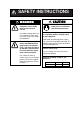
SAFETY INSTRUCTIONS WARNING Do not work inside the equipment unless totally familiar with electrical circuits. Hazardous voltage which can cause electrical shock, burn or serious injury exists inside the equipment. Turn off the power at the mains switchboard before beginning the installation. Post a sign near the switch to indicate it should not be turned on while the equipment is being installed.
This page is intentionally left blank.
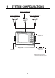
1. SYSTEM CONFIGURATIONS Antenna Unit GPA-018S* Antenna Unit GPA-019S* Antenna Unit GPA-017S** Radar, Echosounder, Autopilot etc.
2. EQUIPMENT LISTS Standards Name Antenna Unit Display Unit Installation Materials Accessories Spare Parts Type GPA-017S GPA-018S GPA-019S GP-150-E-N GP-150-E-A CP20-01900 CP20-01950 FP20-01100 SP20-00500 Q'ty Remarks 1 For DGPS Without Beacon RX With Beacon RX With Antenna Cable See lists Without Antenna Cable at end of manual. 1 1 set 1 set 1 set Options Name Flush Mount Kit S Flush Mount Kit F Antenna Cable Set Antenna Cable Assy.
2. EQUIPMENT LISTS (Continued from the previous page) OP20-32-1 OP20-32 Beacon Receiver Set OP20-33 OP20-34 Rectifier PR-62 DGPS Beacon Receiver Whip Antenna Printer Data Switch Box GR-80 FAW-1.2 PP-505-FP MD-200 000-041-018 000-041-019 000-041-596 000-041-598 000-013-485 000-013-486 000-130-046 000-011-792 - 3 With GPA-018S With whip antenna and OP20-32-1 With GPS-019S Without whip antenna For 100VAC mains For 220VAC mains 1.
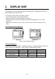
3. DISPLAY UNIT The display unit can be installed with either of four methods as shown below. Refer to the outline drawing at the end of manual. • • • • Locate the unit away from exhaust pipes and vents. The mounting location should be well ventilated. Mount the unit where shock and vibration are minimal. Keep the display unit away electromagnetic field generating equipment such as motor, generator. • Allow sufficient maintenance space and a sufficient slack in cables for maintenance and repair.
3. DISPLAY UNIT Flush mounting type S An optional flush mount kit type S is required. (Name: Flush Mount Kit S, Type: OP20-24, Code No.: 004-393-000) Name Wing bolt Hex. bolt Wing nut Spring washer Flush mount metal Type M4X30 YBSC2 M6X12 SUS304 M4 YBCS2 M6 SUS304 20-013-1111 Code No. 000-804-799 000-162-897-10 000-863-306 000-158-855-10 100-234-230 Qty 4 2 4 2 2 1. Prepare a cutout in the mounting location whose dimensions are 242 (W) X 152 (H) mm. 2. Insert the unit to the cutout. 3.
4. ANTENNA UNIT Mounting Install the antenna unit referring to the installation diagram at end of manual. When selecting a mounting location for the antenna unit, keep in mind the following points. • Select a location out of the radar beam. The radar beam will obstruct or prevent reception of the GPS satellite signal. • Be sure the location offers a clean line-of-sight to satellite.
4. ANTENNA UNIT Taping antenna unit GPA-018S After inserting the whip antenna to the antenna base of GPA-018S, tape the antenna base and whip antenna with self-vulcanizing tape and vinyl tape to reinforce the whip antenna. 1. Wrap the antenna junction point with butyl rubber tape No.15 (NITTO SINKO COOP.) or the equivalent. How to wrap 1) Pull the tape to be about two times in length and wind it up, overlapping by 1/2 the width of the tape. 2) Wrap from bottom to top, i.e.
4. ANTENNA UNIT Extending Antenna Cable Length The standard cable is 15m long. 30m and 50m long extension cable sets are optionally available. ¡Extension cable line-up Fabricate the end of antenna cable and attach the coaxial connector. Details are shown on next page. Antenna Unit GPA-019S Cable length Necessary parts GPA-018S GPA-017S CP20-01700 CP20-02700 CP20-01710 CP20-02710 30 m 50 m 20cm Code no. 004-372-110 004-381-160 004-372-120 004-381-170 : Connector Conversion Cable Assy.
4. ANTENNA UNIT How to attach the N-P-8DFB connector Outer Sheath Armor Inner Sheath Shield 50 Remove outer sheath and armor by the dimensions shown left. Expose inner sheath and shield by the dimensions shown left. 30 Cover with heat-shrink tubing and heat. Cut off insulator and core by 10mm. 10 30 Twist shield end. Clip on clamp nut, gasket and clamp as shown left. Clamp Nut Gasket Clamp (reddish brown) Aluminum Foil Fold back shield over clamp and trim. Trim shield here.
5. WIRING The figure below shows the connection of cables on rear of display unit. CAUTION Ground the display unit to prevent loss of sensitivity and mutual interference.
5. WIRING Grounding The display unit contains several CPUs. While they are operating, they radiate noise, which can interfere with other radio equipment. Ground the unit as follows to prevent it. • The grounding wire should be 1.25sq or larger. • The grounding wire should be as short as possible. External Equipment The DATA1, DATA2, and DATA3 ports are used to connect an external equipment such as autopilot, remote display, navigation equipment.
6. INITIAL SETTINGS Checking Operation 1. Turn on the GP-150. 2. Confirm that "OK" and "BEACON RCVR INSTALLED" are displayed on the self-test display. PROGRAM MEMORY SRAM Internal Battery =OK =OK =OK Confirm that "BEACON RCVR INSTALLED" is displayed when DGPS function is provided. BEACON RCVR INSTALLED DATA 3: DATA OUTPUT Self-test display at equipment start up 3. Press MENU ESC, 8 and 1. Confirm that "OK" are displayed for PROGRAM MEMORY, SRAM, Internal Battery, GPS and BEACON.
6. INITIAL SETTINGS 4. Press W to select Auto. 5. Press the NU/CU ENT key. 6. Press the MENU ESC key. Manual DGPS setup Enter frequency and baud rate of station. 1. 2. 3. 4. 5. 6. 7. 8. 9. Press MENU ESC, 9 and 7 to display the WAAS/DGPS SETUP menu. Press S or T to select MODE and press W to select INT BEACON. Press S or T to select Ref. Station. Press X to select Man. Press T to select Freq. Enter frequency in four digits (283.5 kHz to 325.0 kHz). Press the NU/CU ENT key.
6. INITIAL SETTINGS DGPS Operation checking 1. Press MENU ESC and 7. several times to display the following. 2. Press D3D SAFE Jan 21 2006 23:59’59" U 100m DGPS INTEGRITY STATUS Health: 0 ID: 274 Freq: 323.0 kHz Bit Rate: 200 bps SNR: 21 dB Sig Strength: 83 dB DGPS DATA: BEACON STATION: Signal to noise ratio This value is between 1 to 22. The higher the value, the better the reception of beacon signal. When this value is less than 20, the error is included in the correction data.
6. INITIAL SETTINGS Data format and data output availability Output data sentence of IEC 61162-1 and NMEA 0183 Ver. 1.5/2.0.
6. INITIAL SETTINGS Input data sentence of NMEA 0183 Ver. 1.5/2.0 Checksum is checked if attached, and if any errors are found, the sentence becomes invalid. Talker ID is not distinguished. DBT: Depth below transducer DPT: Depth HDG: Heading, deviation and variation HDM: Heading, magnetic HDT: Heading, true MTW: Water temperature TLL: Target latitude and longitude VBW: Dual ground/water speed VHW: Water speed and heading.
6. INITIAL SETTINGS AGFPA: Autopilot information from FURUNO autopilot equipments Port DATA1 DATA2 Input Output NMEA 0183 IEC 61162-1/NMEA 0183 Ver.1.5/ Ver. 1.5 /2.0 Ver.2.0 AGFPA , DBT, DPT, HDG, AAM, APA, APB, BOD, BWC, BWR, HDM, HDT, MTW, TLL, VBW, BWW, GGA, GLL, GNS, RMB, RMC, VHW VDR, VTG, WCV, WPL, XTE, ZDA, GBS, Rnn, RTE, DTM DATA3 External MOB LOG PULSE Same as the data output form “DATA1” DATA4 DGPS or general data (Selected General data by menu) IEC 61162-1/NMEA 0183 Ver.1.5/ Ver.2.
6. INITIAL SETTINGS DATA 1 output setting 1) Press MENU ESC, 9 and 3. The DATA 1, 3 OUTPUT SETUP menu appears. DATA 1, 3 OUTPUT SETUP Data Fmt. V1.5 V2.0 IEC Talker ID GP LC DE Output Data (00-90 sec) 100% 1. AAM:00 APA:00 APB:04 BOD:00 2. BWC:00 BWW:00 GGA:00 GLL:01 3. RMB:01 RMC:00 VTG:01 WCV:00 4. VDR:00 WPL:00 XTE:00 ZDA:01 5. GNS:00 GBS:01 Rnn:00 RTE:00 200ppm DATA3.
6. INITIAL SETTINGS DATA 2 output setting 1) Press NU/CU MENU, 9 and 4. The DATA 2 OUTPUT SETUP menu appears. DATA2 OUTPUT SETUP Data Fmt. V1.5 V2.0 IEC Talker ID GP LC DE Output Data (00-90 sec) 100% 1. AAM:00 APA:00 APB:04 BOD:00 2. BWR:00 BWW:00 GGA:00 GLL:01 3. RMB:01 RMC:00 VTG:01 WCV:00 4. VDR:00 WPL:00 XTE:00 ZDA:01 5. GNS:00 GBS:01 Rnn:00 RTE:00 : Select ENT : Enter MENU : Escape Setting shown here are default settings.
6. INITIAL SETTINGS Setting DATA 4 to Data Output 1) Press MENU ESC, 9 and 5. The DATA 4 I/O SETUP menu appears. DATA 4 I/O SETUP DATA 4. Level Data To Next Page ENT : Enter 1/2 RS232C Out RS422 Com. DGPS : Select MENU : Escape Appears only when external DGPS receiver is used. DATA 4 I/O SETUP menu 2) 3) 4) 5) 6) Press S or T to select DATA4. Level. Press W or X to select level of external equipment; RS232C or RS422. Press the NU/CU ENT key. Press W or X to select Out.
6. INITIAL SETTINGS Setting DATA 4 to “COM.” (general data) Waypoints and Routes data can be received from a personal computer, through the DATA 4 port. 1) 2) 3) 4) 5) 6) Press MENU ESC, 9 and 5. Press S or T to select DATA4. Level. Press W or X to select level of personal computer; RS232C or RS422. Press the NU/CU ENT key. Press X to select Com. Press T to select To Next Page. The DATA 4 I/O SETUP menu appears. DATA 4 I/O SETUP
6. INITIAL SETTINGS 14)Output data from the computer. When loading data is completed, the cursor shifts to Stop. 15)Press the MENU ESC key. Setting DATA 4 to DGPS An external DGPS receiver can be connected to the DATA 4 port. Follow the procedure below to setup the GP-150 according to the specifications of the DGPS receiver. 1) 2) 3) 4) 5) 6) Press MENU ESC, 9 and 5. Press S or T to select Level. Press W or X to select level; RS232C or RS422. Press the NU/CU ENT key. Press W or X to select DGPS.
7. OPTIONAL DGPS Beacon Receiver Set GR-80 GP-150 GR-80 DATA4 TD-A RS-422* TD-B RD-A RD-B GND Whip Antenna DATA 1 2 3 4 5 6 7 WHT BLK YEL GRN BLU P P 4 3 2 1 7 RD-A RD-B TD-A TD-B GND RS-422 Preamp unit (with 15 m cable) * This connection is required for L/L Auto mode of GR-80. When the GP-150 is connected with Beacon Receiver GR-80, do the setting as follows.
NAME OUTLINE 1 (*1) 1 (*1) 1 1 1 CP20-01900 1 FP20-01100 ** ** ** ** (*1) 1 (略図の寸法は、参考値です。 DIMENSIONS IN DRAWING FOR REFERENCE ONLY.) 2.(*1)の空中線部は仕様により決定されます。 ANTENNA UNIT HAS BEEN DETERMINED BY SPECIFICATION. コ-ド番号末尾の[**]は、選択品の代表コードを表します。 CODE NUMBER ENDING WITH "**" INDICATES THE CODE NUMBER OF REPRESENTATIVE MATERIAL.
NAME OUTLINE 1 (*1) 1 (*1) 1 1 1 CP20-01950 1 FP20-01100 ** ** ** ** (*1) 1 (略図の寸法は、参考値です。 DIMENSIONS IN DRAWING FOR REFERENCE ONLY.) 2.(*1)の空中線部は仕様により決定されます。 ANTENNA UNIT HAS BEEN DETERMINED BY SPECIFICATION. 1.コ-ド番号末尾の[**]は、選択品の代表コードを表します。 CODE NUMBER ENDING WITH "**" INDICATES THE CODE NUMBER OF REPRESENTATIVE MATERIAL.
A-3 CODE NO. 004-369-790-00 TYPE CP20-01101 20AX-X-9404 -1 1/1 工事材料表 INSTALLATION MATERIALS 番 号 NO. 名 称 NAME +トラスタッピンネジ 1 数量 Q'TY 型名/規格 DESCRIPTIONS 略 図 OUTLINE 用途/備考 REMARKS 1シュ 5X20 SUS304 SELF-TAPPING SCREW CODE NO. 4 000-162-608-10 型式/コード番号が2段の場合、下段より上段に代わる過渡期品であり、どちらかが入っています。 なお、品質は変わりませ ん。 TWO TYPES AND CODES MAY BE LISTED FOR AN ITEM. THE LOWER PRODUCT MAY BE SHIPPED IN PLACE OF THE UPPER PRODUCT. QUALITY IS THE SAME. (略図の寸法は、参考値です。 DIMENSIONS IN DRAWING FOR REFERENCE ONLY.
A-4 NAME OF PART OUTLINE 20AI-X-9301 -2 1/1 SP20-00500 BOX NO. U DWG. NO. OR TYPE NO. FGB0-A 125V 2A PBF ヒューズ 1 000-040-717-00 TYPE SPARE PARTS LIST FOR SHIP NO. ITEM NO. CODE NO. FUSE S SETS PER VESSEL E QUANTITY REMARKS/CODE NO. WORKING PER SET PER VES 1 SPARE 3 000-155-849-10 000-549-062-00 FGBO-A 2A AC125V MFR'S NAME FURUNO ELECTRIC (略図の寸法は、参考値です。 CO.,LTD. DIMENSIONS IN DRAWING P DWG NO. 20AI-X-9301 1/1 FOR REFERENCE ONLY.
A-5 Antenna Cable Set CP20-01700 (004-372-110) CP20-01710 (004-372-120) CODE NO. 004-372-420-00 TYPE CP20-01701 20AG-X-9405 -4 1/1 工事材料表 INSTALLATION MATERIALS 番 号 NO. 名 称 NAME 型名/規格 DESCRIPTIONS 略 図 OUTLINE 数量 Q'TY 用途/備考 REMARKS 変換ケーブル組品 1 NJ-TP-3DXV-1 CONVERT CABLE ASSY. CODE NO. 2 000-123-809-00 ビニルテープ 2 NO360 0.2X19X10000 VINYL TAPE CODE NO. 1 000-835-215-00 コネクタ(N) 3 N-P-8DFB-CF CONNECTOR CODE NO. 絶縁テープ 4 SELF-BONDING TAPE Uテープ 000-156-918-10 0.5X19X5M Uテープ 0.
A-6 Antenna Cable Set CP20-02700 (004-381-160) CP20-02710 (004-381-170)
D-1
D-2
D-3
Y. Hatai hatai 2005.12.
D-5 Mar,27'07 R.
D-6 Feb.
D-7 Feb.
D-8
% $ # 60% 25 & O Ǿ 60% 2 60% , & ($ %8 O Ǿ 0 , 0 2 &($ 60% 2 60% , )2# 5 )2# 5 ⓨਛ✢ㇱ #06'00# 70+6 60% 2 �# �# , , 6& # #06 6& $ )0& +'% 0/'# 4& * 4& % 0% )0& )25 #06 �# , 6& # 6& $ +'% 0/'# 4& * 4& % 0% )0& ฃାṶ▚ㇱ &+52.#; 70+6 )2 )0& 016' 5*+2;#4& 5722.; 126+10 %100'%614 2.7) (+66'& #6 (#%614; 5'.'%6 (41/ /'07 5'.
The paper used in this manual is elemental chlorine free. ・FURUNO Authorized Distributor/Dealer 9-52 Ashihara-cho, Nishinomiya, 662-8580, JAPAN Telephone : +81-(0)798-65-2111 Fax : +81-(0)798-65-4200 All rights reserved. Printed in Japan A : FEB . 2006 D : NOV . 06, 2008 Pub. No.