Back COLOR GPS/PLOTTER GP-7000
The paper used in this manual is elemental chlorine free. FURUNO Authorized Distributor/Dealer 9-52 Ashihara-cho, Nishinomiya 662-8580, JAPAN Telephone : 0798-65-2111 Fax 0798-65-4200 : All rights reserved. Printed in Japan FIRST EDITION :AUG. : AUG. 2004 B2 Pub. No. OME-44290 ( AKMU ) GP-7000 : OCT.
IMPORTANT NOTICE • No part of this manual may be copied or reproduced without written permission. • If this manual is lost or worn, contact your dealer. • The contents of this manual and equipment specifications are subject to change without notice. • The example screens (or illustrations) shown in this manual may not match the screens you see on your display. The screen you see depends on your system configuration and equipment settings.
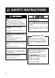
SAFETY INSTRUCTIONS WARNING Do not open the equipment. Hazardous voltage which can cause electrical shock, burn or serious injury exists inside the equipment. Only qualified personnel should work inside the equipment. Do not disassemble or modify the equipment. Fire, electrical shock or serious injury can result. Immediately turn off the power at the switchboard if the equipment is emitting smoke or fire. Continued use of the equipment can cause electrical shock. Do not operate the equipment with wet hands.
FOREWORD Congratulations on your choice of the FURUNO GP-7000 COLOR GPS/PLOTTER. We are confident you will see why the FURUNO name has become synonymous with quality and reliability. For over 50 years FURUNO Electric Company has enjoyed an enviable reputation for innovative and dependable marine electronics equipment. This dedication to excellence is furthered by our extensive global network of agents and dealers.
TABLE OF CONTENTS FOREWORD ........................................................................................................ iii SYSTEM CONFIGURATION................................................................................ vi 1. OPERATIONAL OVERVIEW ......................................................................... 1-1 1.1 Display Unit Controls ......................................................................................................1-1 1.2 Loading an SDTM Chart Card........
3.7 Erasing Track................................................................................................................. 3-4 4. WAYPOINT..................................................................................................... 4-1 4.1 Entering Waypoints........................................................................................................ 4-1 4.1.1 Entering a waypoint at own ship position or cursor position............................... 4-1 4.1.
.3 ADVANCED Menu ..........................................................................................................8-7 8.4 INFO Menu.....................................................................................................................8-9 8.5 FIND Menu .....................................................................................................................8-9 9. DATA TRANSFER.......................................................................................... 9-1 9.
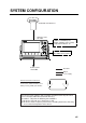
SYSTEM CONFIGURATION ANTENNA UNIT GPA-017 DISPLAY UNIT GP-7000 NMEA1 and NMEA2 ports: Radar, autopilot, video sounder, temperature indicator, etc. PC/NMEA IN port: PC, NMEA device, buzzer Power Source 12-24 VDC : Standard : Option : User Supply How to remove the hard cover Place your thumbs at the center of the cover, and then lift the cover while pressing it with your thumbs. This GPS receiver complies with Canadian standard RSS-210 (Low Power License-Exempt Radio communication Devices).
This page is intentionally blank.
1. OPERATIONAL OVERVIEW This chapter acquaints you with the basics of your unit–from turning on the power to the soft key menu operation. 1.1 Display Unit Controls RANGE key Cursor pad RANGE DISP MENU See below. SAVE MOB ENTER knob GOTO PUSH TO ENTER WPT CLEAR POWER BRILL Card slot Soft keys Opens the DISPLAY MODE menu. Enters waypoint or MOB mark. Brief press: Sets/releases the the destination. Long press: Outputs the TLL data. Shows the route list.
1. OPERATIONAL OVERVIEW 1.2 Loading an SDTM Chart Card Your unit reads C-MAP NT+ /NT MAX TM charts, stored on SDTM cards. Insert the appropriate chart card for your area before turning the power on to show chart data automatically. Note 1: Static electricity can be passed through your fingers to a card and destroy the contents of the card. To prevent this, always touch a metallic object, such as a steel desk, before handling an SDTM card. Note 2: Do not insert or remove a card while the power is on.
1. OPERATIONAL OVERVIEW 1.3 Turning the Power On/Off Turning the power on Press the [POWER/BRILL] key until you hear a click and a beep. When the unit is turned on, it proceeds in the sequence shown in the figure below. GP-7000 GPS PLOTTER FURUNO ELECTRIC CO., LTD.
1. OPERATIONAL OVERVIEW 1.4 Adjusting Brilliance and Contrast You can adjust display brilliance and contrast as shown below. 1. Press the [POWER/BRILL] key momentarily. The BACKLIGHT window appears. BACKLIGHT ENTER TO SET Backlight window 2. Rotate the [ENTER] knob to adjust. Rotate clockwise to raise the setting or counterclockwise to decrease it. To escape from this window without adjusting, press the [CLEAR] or [POWER/BRILL] key, or wait three seconds to let the equipment close it automatically. 3.
1. OPERATIONAL OVERVIEW 1.5 Selecting a Display Nine screen displays are available as shown figure in below. 1. Press the [DISP] key to show the DISPLAY MODE screen. DISPLAY MODE TURN KNOB TO SELECT DISPLAY MODE AND PRESS KNOB TO ENTER. Display mode screen 2. Use the cursor pad or [ENTER] knob to select a mode. To escape from the display mode screen without changing the display mode, press the [DISP] key. 3. Press the [ENTER] knob to set the new display mode. 1.
1. OPERATIONAL OVERVIEW 1.7 MOB Mark 1.7.1 Entering the MOB mark, setting MOB as destination The MOB (Man Overboard) mark functions to mark man overboard position. You can inscribe this mark from any mode. MOB mark MOB Range, bearing MOB Man overboad Current position MOB information Distance and range to MOB position 162.5°M 0.49 nm MOB concept 1. Press and hold down the [MOB/WPT] key immediately for about three seconds when someone falls onboard, to show the display below.
1. OPERATIONAL OVERVIEW 1.7.2 Deleting the MOB mark 1. Operate the cursor pad to place the cursor on the MOB mark, and then press the STOP soft key to cancel the navigation to the MOB mark. 2. Press the DELETE soft key to show the confirmation window. 3. Choose “YES”, and then press the [ENTER] knob to delete the MOB mark. 1.8 Menu Operation Most operations are carried out from the menu bar. The menu bar is opened or closed with the [MENU] key.
1. OPERATIONAL OVERVIEW English Italiano Francais Deutsch Espanol Norsk Svensk Portuguese Language option window 4. Rotate the [ENTER] knob to choose the option desired and then press the [ENTER] knob. To cancel, press the [CLEAR] key. 5. To close all menus and option windows, press the [MENU] key. To close option windows one by one, press the [CLEAR] key. Using the cursor pad 1. Press the [MENU] key to show the menu bar. Menu Bar GENERAL PLOTTER MAP ALARMS ADVANCED INFO FIND Menu bar 2.
1. OPERATIONAL OVERVIEW English Italiano Francais Deutsch Espanol Norsk Svensk Portuguese Language option window 4. Press ▼ to choose an option and then press ► to close the window. To cancel, press ◄. 5. To close all menus and option windows, press the [MENU] key. To close option windows one by one, press the [CLEAR] key. 1.
1. OPERATIONAL OVERVIEW Note: You can return the value to zero by pressing the CLR FLD soft key. 8. Enter SPEED, DATE and TIME. 9. Rotate the [ENTER] knob to choose CURSOR CONTROL and then push the [ENTER] knob. 10. Rotate the [ENTER] knob to choose On or Off as appropriate and then push the [ENTER] knob. When On is selected, you can set course value (◄ ►) and speed value (▲ ▼) on the plotter display. 11. Rotate the [ENTER] knob to choose SELECT POSITION and then push the [ENTER] knob.
2. PLOTTER DISPLAYS 2.1 Presentation Modes The plotter display mainly shows chart, ship’s track, waypoints, and navigation data. Three types of display presentations are provided for the normal plotter display: north-up, course-up and auto course-up. To change the mode, use the presentation mode selection soft key, which is the leftmost soft key. 2.1.1 North-up Press the NORTH UP soft key to show the north-up display. North (zero degree) is at the top of the display.
2. PLOTTER DISPLAY 2.1.2 Course-up Press the COURSE UP soft key to show the course-up display. When destination is set it is at the top of the screen, and the north mark appears at the upper right side of the screen and points to north. When destination is not set, the course is upward on the screen at the moment the course-up mode is selected. N 0001WP 1 nm COURSE UP NAVDATA OFF CENTER MAP SETUP SEARCH Plotter display, course-up mode 2.1.
2. PLOTTER DISPLAY 2.2 Cursor 2.2.1 Turning on the cursor, shifting the cursor Press the cursor pad to turn the cursor on, and the cursor appears at the own ship’s position. Operate the cursor pad to shift the cursor. The cursor moves in the direction of the arrow or diagonal pressed on the cursor pad. Cursor state determines what data is shown in the NAVDATA window. This window can be enabled or disabled by pressing the NAVDATA ON/NAVDATA OFF soft key.
2. PLOTTER DISPLAY 2.2.3 Displaying data Besides its fundamental functions of providing position data, the cursor can also provide data for chosen caution area, depth area, source of data, etc. Further, you can display information about an icon by placing the cursor on it. 1. Press the cursor pad to turn the cursor on. 2. Use the cursor pad to place the cursor on the position desired. The object information window appears. Object Info Wreck Object information window (ex. wreck) 3.
2. PLOTTER DISPLAY 2.4 Navigation Data Display The navigation data display provides generic navigation data, and it is shown in combination displays. Appropriate sensors are required. Bars (- -) appear when corresponding sensor is not connected. Course Position Speed Depth LATITUDE LONGITUDE 22º03.730N 137º57.870E SOG COG TRIP 12.0KTS 7º M 111.5 nm DATE TIME Apr/17/04 12:28 AM DEPTH TEMP 22.5 Ft 10.
2. PLOTTER DISPLAY 2.5 Compass Display The compass display, shown in combination displays, provides steering information. The compass rose shows two triangles: the red triangle shows own ship’s course and the black triangle, which moves with ship’s course, shows the bearing to destination waypoint. The water temperature and depth graphs, which require appropriate sensors, shows the latest 10 minutes of water temperature and depth data.
2. PLOTTER DISPLAY 2.6 Highway Display The highway display, shown in combination display with the plotter screen, provides a graphic presentation of ship’s track along intended course. It is useful for monitoring ship’s progress toward a waypoint. The own ship marker shows the relation between your vessel and intended course. Current time TIME* 12:28AM Speed SOG* 12.
2. PLOTTER DISPLAY 2.7 GPS Status Display The GPS status display provides data on the GPS satellites. Position LONGITUDE LATITUDE 33 18.426N HDOP DOP value SOG Kts TIME DATE Apr/02/04 1.00 12.5 ACQUIRING 131 48.608W 12:09 AM 07 28 14 25 11 31 01 07 11 14 20 25 31 -- -28 -- -- Receive signal level: Bars show satellite signal level. Satellites in brown are used in fixing position. 01 Estimated position in the sky, and satellite number in brown circle is used for positioning.
2. PLOTTER DISPLAY 2.8 Tide, Celestial Display Your plotter provides for calculation of the tide heights for any date. Additionally it displays the time of sunrise, sunset, moonrise and moonset. Nearest Tide Station: High Water Low Water --------- From tide - -.- - nm Sunrise: Sunset: Moonrise: Moonset: 03:50 PM U 01:49 AM U 10:29 AM U 10:07 PM U -.--.-- Ft Ft --- M Moon phase 50% Date Time 33 20. 435N 131 48.
2. PLOTTER DISPLAY 2.9 Graph Display Four graphs can be displayed alternately on the half-screen of the LCD: depth, wind, water temperature and SOG (speed). Press the GRAPH TYPE soft key to choose display graphs in the sequence shown below. Note: Appropriate sensors required to display graphs. Wind Graph Page 2 of 4 Depth Graph Page 1 of 4 9.6 Ft 3.1 knot GRAPH TYPE soft key 10.2 4.2 20.2 3.2 30.2 2.2 40.2 03:33 1.
2. PLOTTER DISPLAY 2.10 Wind Display Your plotter can show the graphical wind indicator when the appropriate data is input. WIND HEAD TRUE 0 30 7º M 30 60 60 --90 90 - - - Kts 120 120 150 180 150 Wind display Selecting the wind direction indication format The wind direction can be selected to true or apparent. 1. Press the [MENU] key to show the menu bar. 2. Rotate the [ENTER] knob to choose GENERAL and then push the [ENTER] knob. 3.
2. PLOTTER DISPLAY 2.11 NAVDATA Window The second soft key from the left functions to control the NAVDATA window. Each press of the key changes this soft key label in the sequence of NAV DATA, NAV+CUR and OFF. NAVDATA window Customizing the NAVDATA window 1. Press the NAV DATA soft key to show the NAVDATA window if it is not already shown. 2. Press and hold the [MENU] key down for two seconds. The data beneath the cursor position is shown in reverse video. 3.
3. TRACK Your ship’s track is plotted on the screen using navigation data fed from the internal GPS navigator. This chapter shows you what you can do with track, from turning it on or off to changing its plotting interval. In the default setting, own ship’s track is turned on and is displayed in black. 3.1 Selecting Active Track Your plotter can plot up to five track lines. It can be useful to have multiple track lines to distinguish tracks according to date or course.
3. TRACK 5. Rotate the [ENTER] knob to choose ACTIVE TRACK and then push the [ENTER] knob. 6. Rotate the [ENTER] knob to choose the desired number of own ship tracks to use, from among 1 to 5. 7. Press the SAVE soft key. 8. Press the [MENU] key to close the menu. 3.2 Displaying Track To display track line on the screen, do the following. 1. Press the [MENU] key to show the menu bar. 2. Rotate the [ENTER] knob to choose PLOTTER from the menu bar and then push the [ENTER] knob. 3.
3. TRACK 3.5 Hiding the Track The track lines can be hidden (but recorded). This function is useful when there are too many tracks to distinguish on the screen and it is hard to distinguish one from another. 1. Choose TRACK from the PLOTTER menu and then push the [ENTER] knob. 2. Choose VISIBLE and then push the [ENTER] knob. 3. Rotate the [ENTER] knob to select On. To re-display the track, choose Off. 4. Press the [MENU] key to close the menu. 3.
3. TRACK 3.6.2 Track plotting interval 1. Choose TRACK from the PLOTTER menu. 2. Choose DISTANCE or TIME as appropriate and then push the [ENTER] knob. 1sec 5 sec 10 sec 30 sec 1 min 5 min 10 min 30 min 1h 0.01 0.05 0.1 0.5 1.0 2.0 5.0 10.0 Distance window Time window Interval windows 3. Rotate the [ENTER] knob to select setting. 4. Push the [ENTER] knob. 5. Press the [MENU] key to close the menu. 3.7 Erasing Track This section shows you how to erase the active track. 1.
4. WAYPOINT In navigation terminology, a waypoint is a particular location on a voyage whether it be a starting, intermediate or destination point. A waypoint is the simplest piece of information your equipment requires to get you to a destination, in the shortest distance possible. This unit has 2,000 waypoints into which you can enter position information.
4. WAYPOINT 4. Rotate the [ENTER] knob to choose the desired alphanumeric character. You can clear all digits in the field by pressing the CLR FLD soft key. 5. Press ► to move the cursor to the next digit, and then rotate the [ENTER] knob to choose the character desired. 6. Repeat steps 4 and 5 to complete the name. (Max. 12 characters) 7. Press the SAVE soft key and then rotate the [ENTER] knob to choose the LATITUDE/LONGITUDE section. 8. Push the [ENTER] knob. 9.
4. WAYPOINT 4.1.2 Entering a waypoint from the waypoint list You can manually enter waypoint position from the waypoint list as follows. 1. Press the [MENU] key to show the menu bar. 2. Rotate the [ENTER] knob to choose PLOTTER and then push the [ENTER] knob to show the PLOTTER menu. TRACK ROUTES WAYPOINTS MEMORY CARD TRACK WAYPOINTS 11999/12000 12/2000 Number of tracks and waypoints in use Plotter menu 3. Rotate the [ENTER] knob to choose WAYPOINTS and then push the [ENTER] knob.
4. WAYPOINT 4.1.3 Entering a waypoint/MOB mark with an external event switch If the equipment is equipped with an external event switch you may choose what mark is inscribed on the screen when the switch is pressed. The choices are Waypoint, MOB mark or Off (no event switch is connected). 1. Press the [MENU] key to show the menu bar. 2. Rotate the [ENTER] knob to choose ADVANCED from the menu bar and then push the [ENTER] knob. 3.
4. WAYPOINT 4.2 Editing Waypoint Data Waypoint data may be edited from the waypoint list or directly from the plotter display. 4.2.1 Editing waypoint data from the waypoint list 1. Press the [MENU] key to show the menu bar. 2. Rotate the [ENTER] knob to choose PLOTTER and then push the [ENTER] knob. 3. Rotate the [ENTER] knob to choose WAYPOINTS and then push the [ENTER] knob to show the WAYPOINT LIST. 4. Press the cursor pad (▲▼) to choose the waypoint you want to edit. 5.
4. WAYPOINT 4.3 Erasing Waypoints Waypoints can be erased from the waypoint list or directly from the plotter display. 4.3.1 Erasing a waypoint directly from the plotter display 1. Press the cursor pad to place the cursor on the waypoint you want to delete. 2. Press the DELETE soft key. The following window appears. WARNING Delete 0001WP Are you sure? YES NO 3. Push the [ENTER] knob. The color of the selected waypoint at step 1 changes to blue. To erase completely, press the [RANGE] key. 4.3.
4. WAYPOINT 4.4 Searching, Sorting Waypoints You can search and sort waypoints on the waypoint list as follows. Searching by waypoint name 1. 2. 3. 4. Open the WAYPOINT LIST. Rotate the [ENTER] knob to choose SEARCH at the bottom of the screen. Push the [ENTER] knob. Enter the waypoint name you want to find, and then press the SAVE soft key. The cursor moves on the chosen waypoint name on the list. 5. Press the [CLEAR] key to close the list. Sorting waypoints 1. Open the WAYPOINT LIST. 2.
4. WAYPOINT 4.5 Other Waypoint List Functions This section shows you how to execute the various functions available on the WAYPOINT LIST. 4.5.1 Filtering waypoints by mark shape You may filter waypoints in the waypoint list by mark shape. This is useful when you are looking for waypoints of a specific shape. 1. Open the WAYPOINT LIST. 2. Rotate the [ENTER] knob to choose ICON at the bottom of screen. 3. Push the [ENTER] knob to show the ICON window. ICON SELECT ALL Icon window 4.
4. WAYPOINT 4.5.2 Hiding or showing waypoints Waypoints can be shown or hidden individually or collectively on the plotter display as below. 1. Open the WAYPOINT LIST. 2. Press the cursor pad (▲▼) to choose the waypoint you want to show or hide. All waypoints can also be shown or hidden. 3. Rotate the [ENTER] knob to choose MODE at the bottom of screen, and then push the [ENTER] knob. MODE SHOW ICON HIDE SHOW ALL ICON ALL HIDE ALL Mode window 4. Rotate the [ENTER] knob to choose option desired.
4. WAYPOINT This page is intentionally left blank.
5. ROUTE Often a trip from one place to another involves several course changes, requiring a series of route points (waypoints) which you navigate to, one after another. The sequence of waypoints leading to the ultimate destination is called a route. 5.1 Entering Routes You can store up to 200 routes and a route may consist of 35 points. 1. Press the [MENU] key to show the menu bar. 2. Rotate the [ENTER] knob to choose PLOTTER and then push the [ENTER] knob to show the PLOTTER menu.
6. ROUTE Range between two waypoints ROUTE NAME:0001RT______ Route name and comment COMMENT : 17:33_ JUL1003 LEG 1 00 73WP______ 14:09_APR0403 0001WP______ 09:21_JAN1903 NISHINOMIYA_ 10:34_JAN1903 0008WP______ 15:07_JAN1903 0018WP______ 16:49_APR0103 0022WP______ 11:12_APR0603 34 41.895 ’N 135 21.109 ’W 34 43.776 ’N 135 17.883 ’W 34 46.007 ’N 135 19.521 ’W 34 80.398 ’N 135 35.354 ’W 34 28.361 ’N 135 49.239 ’W 34 24.242 ’N 135 46.753 ’W SORT SEARCH Push [MENU] key to execute.
5. ROUTE 5.3 Connecting Routes Two routes which you have created can be connected as follows to form a new route. 1. Open the route menu. 2. Rotate the [ENTER] knob to choose CONNECT at the bottom of screen and then push the [ENTER] knob. The connect route menu appears. 0001RT______ LENGTH CONNECT ROUTE 3.
6. ROUTE 5.4 Inserting Waypoints Waypoints can be inserted in a route as follows: Inserting a waypoint from the route list 1. Show the route list. 2. Press the cursor pad (▲▼) to choose a route. 3. Rotate the [ENTER] knob to choose EDIT at the bottom of screen and then push the [ENTER] knob to show the route menu.
5. ROUTE Inserting a waypoint from the plotter display You can insert a waypoint in a route directly on the screen. 1. Press the cursor pad to place the cursor on the desired line between waypoints in a route. The window below appears. ROUTE: 1 [0001RT] 0001WP - 0002WP DST: 4.74 nm BRG: 102 M Leg window (ex.) 2. Press the INSERT soft key. The selected line (dashed) turns red. 3. Operate the cursor pad to place the cursor on an existing waypoint and then push the [ENTER] knob. 4. Press the SAVE soft key.
6. ROUTE 5.6 Information on Route Report The route report provides various information about routes, such as time distance and necessary fuel to go to a waypoint in route. 1. Open the route list. 2. Press the cursor pad (▲▼) to choose the route desired. 3. Rotate the [ENTER] knob to choose REPORT at the bottom of screen and then push the [ENTER] knob. The route report for the route appears.
5. ROUTE Entering the speed for TIME column Enter speed to be used for TIME calculation. 1. Show the route report. 2. Rotate the [ENTER] knob to choose SPEED at the bottom of screen and then push the [ENTER] knob to show the SPEED window. SPEED 1 0.0 kt You can change the digit by pressing the cursor pad (◄►). 3. Enter the ship’s speed and then SAVE soft key.
6. ROUTE 5.8 Searching Routes You can search for a route through the route list or on the plotter display. Searching a route through the route list 1. Open the route list. 2. Rotate the [ENTER] knob to choose SEARCH at the bottom of screen. 3. Push the [ENTER] knob. The NAME window appears. NAME 0001RT Name window 4. Enter the route name you want to search. You can change the digit by pressing the cursor pad (◄►). 5. Push the SAVE soft key. The selected route name is shown at the top of the list. 6.
6. NAVIGATION This chapter shows you how to get to a desired destination by using “quick points”, waypoints, port services and routes. 6.1 Navigating to Quick Points The quick points feature allows you to navigate to a cursor-selected location. Each time a quick point is entered, the previous quick point is written over. Navigating to a quick point 1. Operate the cursor pad to place the cursor at the location where you want to enter a quick point. 2. Press the [TLL/GOTO] key to show the GO TO window.
6. NAVIIGATION Navigating a quick route 1. Press the cursor pad to place the cursor at the position where you want to enter a waypoint. 2. Press the [ROUTE] key to show the new waypoint window. 3. If necessary, arrange the waypoint data. 4. Press the SAVE soft key. 5. Repeat steps 1 through 4 to complete the route. Maximum 35 points can be entered. To erase a waypoint, place the cursor on the waypoint which you want to erase and then press the DELETE soft key. 6.
6. NAVIGATION Navigating to ports, port service C-MAP NT+/NT MAXTM chart cards have a port service list which shows services available at ports and harbors. You can use the list to set destination as follows. 1. Press the [MENU] key to show the menu bar. 2. Rotate the [ENTER] knob to choose FIND and then push the [ENTER] knob. 3. Rotate the [ENTER] knob to choose PORT SERVICES or PORT and then push the [ENTER] knob to show the appropriate window. Port service window Port window 4.
6. NAVIIGATION 6.2 Navigating to Waypoints You can select an existing waypoint as destination by cursor, by name or through the WAYPOINT LIST. To cancel the navigation, locate the cursor on the destination waypoint, and then press the STOP soft key. Selecting waypoint by cursor 1. Press the cursor pad to place the cursor on the waypoint which you want to set as destination. 2. Press the [TLL/GOTO] key. A line runs between waypoint selected and own ship’s position.
6. NAVIGATION 6.3 Following a Route You can follow a route as follows. Setting a complete route as destination This method enables you to navigate from the first waypoint of a route. 1. Press the cursor pad to place the cursor at the location not occupied by waypoint. 2. Press the [TLL/GOTO] key to show the GO TO window. 3. Rotate the [ENTER] knob to choose ROUTE and then push the [ENTER] knob to show the SELECT ROUTE window.
6. NAVIIGATION Skipping route waypoints In some instances you may want to “skip” waypoints while following a route. In the figure below, for example, the vessel has decided to navigate from waypoint 05 to 03, skipping waypoint 04. Waypoint 1 Waypoint 2 PORT 1 Waypoint 3 Waypoint 4 New course line Waypoint 5 PORT 2 Waypoint 6 1. Press the cursor pad to place the cursor on a waypoint which is part of the route. 2. Press the ROUTE LIST soft key to show the route list. 3.
7. ALARMS The plotter section has seven conditions which generate both audio and visual alarms: arrival, XTE, temperature, depth, anchor, STW and grounding alarms. When an alarm is violated both audio and visual alarms are released. You may silence the audio alarm with the [CLEAR] key. The visual alarm remains on the screen until the offending alarm is deactivated or the reason for the alarm has disappeared. You may set up the alarms on the ALARM menu. 6. Press the [MENU] key to show the menu bar.
7. ALARM 7.1 Audible Alarm On/Off Audio and visual alarms are released whenever an alarm setting is violated. You can enable or disable the audio alarm as follows: 1. Press the [MENU] key to show the menu bar. 2. Rotate the [ENTER] knob to choose ALARMS and then push the [ENTER] knob to show the ALARMS menu. 3. Rotate the [ENTER] knob to choose AUDIBLE ALARM and then push the [ENTER] knob. Internal Internal+External Off 4.
7. ALARMS 7.3 XTE (Cross-Track Error) Alarm The XTE alarm warns you when your boat is off its intended course. Note that this alarm is available only when a destination is set. Own ship position Alarm setting Destination waypoint Intended course : Alarm How to XTE alarm works 1. Open the ALARMS menu. 2. Rotate the [ENTER] knob to choose XTE ALARM and then push the [ENTER] knob. Off 0.00 nm 3. Rotate the [ENTER] knob to choose “x.xx (value) nm” and then push the [ENTER] knob. 4.
7. ALARM 7.4 Temperature Alarm Note: This alarm requires water temperature data. There are two types of water alarms: Within Range and Out of Range. The Within Range alarm sounds when the water temperature is within the range set, and the Out of Range sounds when the water temperature is higher or lower than the range set. 1. Open the ALARMS menu. 2. Rotate the [ENTER] knob to choose TEMPERATURE ALARM and then push the [ENTER] knob. Off Max Min +32.00 F +32.00 F 3.
7. ALARMS 7.5 Anchor Alarm The anchor alarm informs you that your boat is moving when it should be at rest. Own ship's Setting range position : Alarm How the anchor watch alarm works 1. Open the ALARMS menu. 2. Rotate the [ENTER] knob to choose ANCHOR ALARM and push the [ENTER] knob. Off 0.00 nm 3. Rotate the [ENTER] knob to choose “x.xx (value) nm” and then push the [ENTER] knob. 4. Rotate the [ENTER] knob to enter the value. 5. Push the SAVE soft key and [MENU] key in order to close the menu. 7.
7. ALARM 7.7 Depth Alarm Note: This alarm requires depth data. The depth alarm sounds when the depth is within the alarm range set. 1. Open the ALARMS menu. 2. Rotate the [ENTER] knob to choose DEPTH ALARM and then push the [ENTER] knob. Off Depth 0000.0 Ft Range 0010.0 Ft 3. Confirm that the cursor is located at the top line, and then push the [ENTER] knob. Off On 4. 5. 6. 7. Rotate the [ENTER] knob to choose On and then push the [ENTER] knob.
7. ALARMS 7.8 Grounding Alarm The grounding alarm sounds when there is an object on chart data which is within the depth range and depth set. Further, you can know what kind of object is causing the alarm when it enters in the range. 1. Open the ALARMS menu. 2. Rotate the [ENTER] knob to choose GROUNDING ALARM and then push the [ENTER] knob. 3. Rotate the [ENTER] knob to choose “xx (value) ft” and then push the [ENTER] knob. 4. Enter the depth value desired. 5. Press the SAVE soft key. 6.
7. ALARM This page is intentionally left blank.
8. CUSTOMIZING YOUR UNIT This chapter describes the various options which allow you to customize the plotter section to suit your needs. 8.1 GENERAL Menu The GENERAL menu provides the basic setup for the unit.
8. CUSTOMIZING YOUR UNIT DATE FORMAT Chooses date notation; MM-DD-YY or DD-MM-YY. AUTO INFO Chooses what data is available with the cursor; Off, On Points or On All. On Points: Data for selected chart symbol, for example, lighthouse or harbor. All Points: Data for any location within the area covered by the chart. SHIP ICON Chooses the shape of own ship marker; , + or . WIND GRAPH See section 2.10 for details about the wind display.
8. CUSTOMIZING YOUR UNIT PERSPECTIVE VIEW Chart data is projected in perspective mode, for 3D simulation, during navigation. DYNAMIC NAV-AIDS Shows the flash from the lighthouse/buoy with the actual interval. MIXING LEVELS Detailed chart data and coarse chart data may be incorporated and displayed in areas where they are mixed. With detailed chart data displayed and own ship position or cursor position as reference, coarse chart data area of low accuracy is shown in white when this setting is disabled.
8. CUSTOMIZING YOUR UNIT DANGERS Shown in red when the GROUNDING alarm detects the high-risk object (listed in the grounding report) when the GROUNDING alarm is turned on. CAUTIONS Shown in red when the GROUNDING alarm detects the low-risk object when the GROUNDING alarm is turned on. NAV AIDS PRESENTATION Chooses what kind of navaids symbols to display, International or US.
8. CUSTOMIZING YOUR UNIT MAP CONFIGURATION DISPLAY MODE Chooses the map to display; Full, Medium, Low, Tides or Custom. “Full” shows all data in the chart card. Note that data can be arranged only when Custom is chosen here. As for each items, refer to the handbook for C-MAP.
8.
8. CUSTOMIZING YOUR UNIT 8.3 ADVANCED Menu The ADVANCED menu calibrates data. FIX Item FIX CORRECTION COMPUTE CORRECTION CORRECTION OFFSET POSITION FILTER SPEED FILTER Settings GPS-generated position may be off by some seconds because of various factors. In this case, you can automatically correct GPS position by selecting On. Corrects the GPS antenna position. After placing the cursor at the own ship’s true position, select this item. Corrects the GPS antenna position manually.
8. CUSTOMIZING YOUR UNIT NAVIGATE Item COORDINATE SYSTEM MAP DATUM MAP ORIENTATION MAP ORIENTATION RES Settings Choose the coordinate display method among ddd mm ss, ddd mm.mm, ddd mm.mmm and ddd.ddddd for latitude, or TD. Geodetic datum is a reference for geodetic survey measurements consisting of fixed latitude, longitude and azimuth values associated with a defined station of reference.
8. CUSTOMIZING YOUR UNIT 8.4 INFO Menu This menu shows the detailed information for the location selected by the cursor. Choose a location, and then open the INFO menu and select item. 8.5 FIND Menu You can find objects on the chart data in use dividing with the category of TIDE STATION, WRECKS and OBSTRUCTIONS. Choose the appropriate category from the FIND menu, and then push the [ENTER] knob.
8. CUSTOMIZING YOUR UNIT This page is intentionally left blank.
9. DATA TRANSFER This chapter provides information for saving and replaying data to and from memory cards, and updating and downloading data. 9.1 Memory Card Operations The memory cards store these data: waypoints, routes and track. 9.1.1 Selecting the card slot to use There are two card slots, upper and lower. Choose the one to use for memory cards as follows: 1. Press the [MENU] key to show the menu bar. 2. Rotate the [ENTER] knob to choose PLOTTER and then push the [ENTER] knob.
9. DATA TRANSFER 9.1.2 Formatting memory cards Before you can use a memory card it must be formatted. This prepares the card for use with the system. Note that formatting a memory card erases all data from the card. 1. Insert the memory card to the selected slot. 2. Open the MEMORY CARD LIST. 3. Rotate the [ENTER] knob to choose INITIALIZE at the bottom of screen and then push the [ENTER] knob. WARNING FORMAT USER CARTRIDGE All data will be lost. Are you sure? YES NO 4.
9. DATA TRANSFER 9.1.4 Playing back data from a memory card Data (track, waypoints, routes) can be loaded from a memory card and displayed on the screen. This feature is useful for observing past data. 1. Insert the memory card to play back into the selected slot. 2. Open the MEMORY CARD list. 3. Rotate the [ENTER] knob to choose LOAD and then push the [ENTER] knob. 9.
9. DATA TRANSFER 4. When receiving data, follow steps shown below. a) Choose NMEA 1 INPUT, NMEA 2 INPUT or RS232 3 INPUT appropriately, and then push the [ENTER] knob. b) Communication format between this unit and PC (or GP-7000/F) should be the same. 5. Press the [CLEAR] key several times to close the window and menus. 6. Open the WAYPOINT LISTS. WAYPOINT LIST SYM NAME ICON MODE TYPE FIND DELETE LATITUDE LONGITUDE LOCATE SORT DST [nm} BRG [M] EDIT SEND MODE NEW RECEIVE Waypoint list 7.
9. DATA TRANSFER 9.2.2 Sending/receiving routes data You may sending/receiving routes as follows. When sending data, set the connected equipment for receiving. Note: All waypoints in a route can be transported with the route. 1. Connect the PC or another GP-7000/F to the equipment. 2. Choose INPUT/OUTPUT from the ADVANCED menu. 3. When sending data, follow steps shown below. a) Choose NMEA 1 OUTPUT, NMEA 2 OUTPUT or RS232 3 OUTPUT appropriately. The sentence window appears.
9. DATA TRANSFER ROUTE LIST N NAME FIND PLOT SEND LENGTH NEW DELETE RECEIVE WAYPOINTS EDIT REVERSE CONNECT RENAME COLOR SELECT COMMENT SEARCH REPORT Route list 7. For sending, press the cursor pad (▲▼) to choose the route desired. 8. Rotate the [ENTER] knob to choose SEND or RECEIVE at the bottom of the screen. SEND: Sending the route chosen at step 8 to external equipment. RECEIVE: Receiving all routes to the internal memory from external equipment. 9. Press the [ENTER] knob to execute.
10. MAINTENANCE & TROUBLESHOOTING 10.1 Maintenance Regular maintenance is important for continued performance. Important points to be checked from time to time are shown below. WARNING Do not open the equipment. Hazardous voltage which can cause electrical shock exists inside the equipment. Only qualified personnel should work inside the equipment. Location Check point Remedy Antenna unit Check for loosened and corroded bolts. Tighten loosened bolts. Replace heavily corroded bolts.
10. MAINTENANCE & TROUBLESHOOTING 10.2 Replacement of Fuse CAUTION Use the correct fuse. Use of a wrong fuse can cause fire or damage the equipment. The fuse on the power cable protects the system from reverse polarity of the ship’s mains and equipment fault. If the fuse blows, find the cause before replacing it. Use only a 3A fuse. Using the wrong fuse will damage the unit and void the warranty. Name Fuse 10.3 Type FGBO-A 3A AC125V Code No.
10. MAINTENANCE & TROUBLESHOOTING 10.4 Simple Troubleshooting This section provides simple troubleshooting procedures which the user can follow to restore normal operation. If you cannot restore normal operation do not attempt to check inside the unit. Any trouble should be referred to a qualified technician. General troubleshooting If … you cannot turn on the power no picture appears there is no response when a key is pressed Then … check for blown fuse.
10. MAINTENANCE & TROUBLESHOOTING 10.5 Diagnostics This section provides the procedures for testing the equipment for proper operation. Four tests are provided: RAM menu, Dim menu, Cartridges and Serial ports. To access the test menu, do the following: 1. Press the [POWER/BRILL] key to turn on the equipment while holding the [CLEAR] key down. 2. Release the [MENU] key when you hear the beep. SYSTEM TEST 1451722-01.02V*.**._** NTSL V5.0.
10. MAINTENANCE & TROUBLESHOOTING 10.5.2 Dim menu The Dim menu checks the contrast and backlight control circuits for proper operation. 1. Rotate the [ENTER] knob to choose “Dim menu” on the SYSTEM TEST. 2. Push the [ENTER] knob to show the Dim window. Contrast Backlight Dim window 3. Rotate the [ENTER] knob to select “Contrast” or “Backlight” as appropriate, and then push the [ENTER] knob. 4. Press the cursor pad to change the setting. 5. Confirm that the contrast or backlight changes appropriately.
10. MAINTENANCE & TROUBLESHOOTING 10.5.4 Serial ports You can confirm the signal input. 1. Rotate the [ENTER] knob to choose Serial port from the SYSTEM TEST. 2. Push the [ENTER] knob to show the Serial port window. Change parameters Input data display Serial port 3. Rotate the [ENTER] knob to choose “Change parameters” and then push the [ENTER] knob. Port: Baud Rate: Data Bits: Parity: Stop Bits: PORT2 4800 8 none 1 4. Enter the settings for the port in use and then push the [CLEAR] key. 5.
10. MAINTENANCE & TROUBLESHOOTING 10.7 Clearing the Memory The memory can be cleared to restart operation with default settings. All tracks, waypoints and routes are deleted and all default menu settings are restored. 1. Turn the power on while holding the [CLEAR] key down. 2. Release the [CLEAR] key when you hear the beep. 3. Rotate the [ENTER] knob to choose “RAM menu” and then push the [ENTER] knob. RAM test RAM clear RAM window 4.
10. MAINTENANCE & TROUBLESHOOTING This page is intentionally left blank.
APPENDIX Menu Tree MENU BAR GENERAL LANGUAGE (English, others) KEYPAD BEEP (Off, On) PALETTE (Normal, SunLight, Night, NOAA) TIME LINE (Infinite, off, 2 min, 10 min, 30 min, 1 hour, 2 hours) TIME REFERENCE (UTC, -19:30 to +19:30 (in 30 min.
APPENDIX 1 ALARMS AUDIBLE ALARM (Off, Internal, Internal+External) ARRIVAL ALARM (Off, 0.00 to 5.39 nm) XTE ALARM (Off, 0.00 to 5.39 nm) TEMPERATURE ALARM (Off, MAX/MIN: -004.00 to +103.98 F) DEPTH ALARM (Off, Depth/Range: 0 to 9999.9 ft) ANCHOR ALARM (Off, 0.00 to 5.39 nm) STW ALARM (Off, MAX/MIN: 000.0 to 539.9 kt) GROUNDING ALARM (Off, 0 to 65 ft) GROUNDING ALARM RANGE (0.25 nm, 0.5 nm, 1.0 nm) GROUNDING ALARM REPORT FISH ALARM (Off, Depth/RANGE: 000.
APPENDIX 3 2 GPS SIMULATION SIMULATION MODE (Off, On) COURSE (0 to 359 ) SPEED (0 to 539 kt, 1.
APPENDIX What is WAAS? WAAS, available in North America, is a provider in the worldwide SBAS (Satellite Based Augmentation System) navigation system. An SBAS provider furnishes GPS signal corrections to SBAS users. Two more SBAS providers are also currently under development, MSAS (Multi-Functional Satellite Augmentation System) for Japan and EGNOS (Euro Geostationary Navigation Overlay Service) for Europe.
APPENDIX World Time Chart art AP-5
APPENDIX This page is intentionally left blank.
SPECIFICATIONS OF GPS PLOTTER/SOUNDER GP-7000 1 GENERAL 1.1 Display 7-inch wide color LCD 1.2 Projection Mercator 1.3 Usable Area 80° latitude or below 1.4 Display Mode Plotter, Nav Data, Highway display, Compass display 1.5 Alarms Arrival and Anchor watch, Cross track error, Temperature, Depth, Grounding, Ship’s speed alarms 2 2.1 GPS RECEIVER Receiving Channels GPS 12 channels parallel, 12 satellites tracking WAAS 1 channel 2.2 Rx Frequency 1575.42 MHz 2.
4.7 5 5.1 Electronic Chart Card C-MAP NT+/MAX chart SD card INTERFACE Input data sentences IEC61162-1 and NMEA 0183 Ver1.5 DBT, DPT, MTW, TLL, WPL, VHW, HDT, HDG, DSC, MWV 5.2 Output data sentences IEC61162-1 or NMEA 0183 Ver1.5 selected on menu $GPAAM, $GPAPB, $GPBOD, $GPBWR, $GPGLL, $GPGTD, $GPHDG, $GPGGA, $GPRMA, $GPRMB, $GPRMC, $GPVTG, $GPXTE, $GPZDA, $GPWPL, $GPMWV, $GPVHW, $GPTLL, $GPRTE, $GPMTW, $GPHSC, $GPWCV, $GPAPA 6 6.1 7 7.1 POWER SUPPLY Display Unit 12-24 VDC: 1.5-0.
INDEX A alarms .............................................. 7-1, 10-18 anchor ......................................................7-5 arrival .......................................................7-2 audio ........................................................7-2 depth ........................................................7-6 grounding.................................................7-7 STW .........................................................7-5 temperature ....................................
reversing ..................................................5-8 searching .................................................5-8 S serial ports .................................................10-7 ship icon ......................................................8-2 simulation mode ..........................................1-9 soft keys.......................................................1-5 T track .............................................................3-1 active ....................................