INTERFACE UNIT IF-2500 (TENI, 0307) PUB. No.
SAFETY INSTRUCTIONS CAUTION CAUTION The mounting location should satisfy the following conditions: Sparate from radio transmitter, radar, direction finder (at least 3m). Locate the equipment away from air conditioner vents. Keep the equipment out of direct sunlight. Vibration should be minimal. The location should be free of water spray. Observe the following compass safe distances to prevent deviation of a magnetic compass: Standard compass IF-2500 1.40 m Steering compass 0.
TABLE OF CONTENTS Overview............................................................................................................... 1 Installation materials ........................................................................................... 1 Spare parts ........................................................................................................... 1 Cables ...................................................................................................................
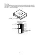
Overview The interface for the dual GPS navigator receives data from two GPS navigators and chooses one to output in accordance with priority order. Output data is converted to NMEA current loop, IEC 61162-1 or contact signal and output.
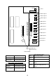
Mounting Selection of output data format This unit does not have power switch. If you do not connect the IF-2500 to power switchboard or circuit breaker, install an external power switch (local supply), locating it near the IF-2500. The output data format is selectable by changing a jumper block; A for IEC61162-1 and B for NMEA. For example, to select NMEA for J4, change the jumper block from A to B on JP401 and JP402. Do the same on J5 thru J9.
Fabrication of CO-SPEVV-SB-C 0.2X2P 75 mm Armor 35 mm Sheath 33 mm Shield 28 mm 3 mm Earth cable Cut unused cores and solder them to shield. 3 mm 15 mm (Supplied) 15 mm 30 mm Heat shrink tube Twist and solder Heat shrink tube How to fabricate the signal cable 3 Fix the cable with the cable clamp at this location.
10-35V J1 Power FUSE 0.
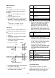
Maintenance CR2 Self test 1 CR4 The unit performs an internal self-check in the following sequence each time power is turned on. 1. LEDs CR7 to CR10 blink twice every 2 seconds. 2. ROM and RAM are tested. 3. LED CR6 blinks every second for normal operation. If an error is detected during the test, the corresponding LED is turned on. CR6 CR7 CR8 CR9 CR10 5. Remove the connector from J4 and plug it into J5, J6, J7 and J8 successively, confirming that CR2 and CR9 light as below for each port.
FURUNO SPECIFICATIONS OF INTERFACE UNIT IF-2500 This equipment is used for distribution of navaids data from navigation equipment. It provides six outputs each from two independent inputs. Alarm signal is also available to distribute three outputs from two independent inputs. 1. Port Input: 2 ports (IEC61162-1) Output: 6 ports (IEC61162-1 or Current loop) Alarm signal Output: 3 ports (Relay contact) 2. Alarm signal Receiving Error Alarm, Cross Track Error Alarm, Arrival Alarm 3.
000-000-993 000-000-992 XH4P-002 000-000-991 XH5P-002 000-802-080 XH6P-002 000-133-817 4X16 SUS304 1シュ 3 (略図の寸法は、参考値です。 DIMENSIONS IN DRAWING FOR REFERENCE ONLY.) (*1) 5 (*1) 1 (*1) 2 4 1 CP14-06300 MJ-A6SPF0012-100 64S4071 000-114-994 (*1) 1 Q'TY SP14-01100 FGMB 0.5A AC125V 000-000-999 IF-2500 DESCRIPTION/CODE № IF-2500 1.(*1)印のユニット及び部品コードは架空コードに付き注文用には使用できません。 (*1)Code numbers are not allowed to order as dummy code. XH CONNECTOR ASSY. XHコネクタ組品 XH CONNECTOR ASSY.
1 2 3 インターフェイスユニット INTERFACE UNIT IF-2500 12-24VDC A VCTF1.25x2C/VH2P,3m,φ7.4 P P 1 2 3 4 5 6 P 1 2 3 4 5 6 CO-0.2x2P OR TTYCS-1 *1 航法装置 NAVIGATOR データ入力 DATA INPUT IEC61162-1 優先順位 (Priority): J2 > J3 CO-0.2x2P OR TTYCS-1 *1 航法装置 NAVIGATOR B C D J1(VH2P) 1 DC+ 2 DC- J4(XH4P) TD-H/TD-B 1 *2 TD-C/TD-A 2 NC 3 GND 4 J2(XH6P) NC J5(XH4P) NC RD-H TD-H/TD-B 1 *2 RD-C TD-C/TD-A 2 NC 3 NC GND 4 GND CO-0.2x2P OR TTYCS-1 *1 P CO-0.