INTEGRATED HEADING SENSOR MODEL PG-1000
C Yo u r L o c a l A g e n t / D e a l e r 9-52, Ashihara-cho, Nishinomiya, Japan Te l e p h o n e : Te l e f a x : 0 7 9 8 - 6 5 - 2 111 0798-65-4200 All rights reserved. Printed in Japan PUB. No. OME-72460 (HIMA) PG-1000 FIRST EDITION H : : JUL. 1997 N O V.
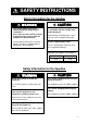
SAFETY INSTRUCTIONS Safety Information for the Installer WARNING CAUTION Turn off the power at the mains switchboard before beginning the installation. Post a sign near the switch to indicate it should not be turned on while the equipment is being installed. Confirm that the power supply voltage is compatible with the voltage rating of the equipment. Fire or electrical shock can result if the power is left on or is applied while the equipment is being installed. Use the supplied power cable.
FOREWORD A Word to PG-1000 Owners Congratulations on your choice of the FURUNO PG-1000 Integrated Heading Sensor. We are confident you will see why the FURUNO name has become synonymous with quality and reliability. For over 50 years Furuno Electric Company has enjoyed an enviable reputation for innovative and dependable marine electronics equipment. This dedication to excellence is furthered by our extensive global network of sales and service.
TABLE OF CONTENTS SYSTEM CONFIGURATION .............................................................. iv SPECIFICATIONS..........................................................................SP-1 1 INSTALLATION 1.1 Equipment List .................................................................................................................... 1 1.2 Selecting Mounting Location .............................................................................................. 2 1.3 Mounting .................
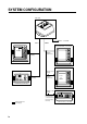
SYSTEM CONFIGURATION PG-1000 10.0 - 35.0 VDC RADAR/ARPA (ex: MODEL1832) AD-10 NMEA GPS NAVIGATOR (ex: GP-1610C) HDG 88.8° Heading Magnetic or true heading Magnetic variation data CURRENT INDICATOR (ex: CI-1000) Magnetic or true heading Heading Magnetic or true heading Magnetic variation data Course CSE 88.8° AUTOPILOT (ex: FAP-300) Magnetic or true heading Heading ON Optional equipment Local Supply iv Deviation at the PG-1000 can be corrected from the Remote Display DD-2000.
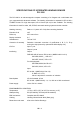
SPECIFICATIONS OF INTEGRATED HEADING SENSOR PG-1000 The PG-1000 is an electromagnetic compass consisting of a fluxgate and a solid-state rate gyro, supported with advanced software. The heading information is outputted in IEC 61162-1 or NMEA format. For high data speed, AD-10 format (25 ms) is also available. The heading information is used for radar, AIS, ECDIS, automatic steering system and other navaids. Heading Accuracy Static ±1.
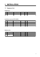
1 INSTALLATION 1.1 Equipment List Standard set No. Name Type 1 Sensor PG-1000-E 2 Installation Materials CP64-02000 Code No. Qty ---- 1 000-040-433 1 Code No. Qty Remarks Refer to table below. Installation materials (CP64-02000) No. Name Type 1 Tapping screw 4x16 SUS304 000-802-080 2 2 Flat washer M4 SUS304 000-864-126 2 3 Power cable 22S0019 000-109-000 1 4 Cable assy. MJ-A6SPF0007-100 000-125-237 1 Type Code No.
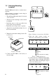
1.2 Selecting Mounting Location BOW 12-24 VDC The PG-1000 must be indoor on the horizontal plane. + - Å~ NMEA AD10 When selecting a mounting location, keep in mind the following points: • The ambient temperature must be between -15°C and 55°C. Grounding Sensor (top view) • Vibration at the mounting location should be minimal. • Install the sensor as far as possible from power cable, ferrous materials. • Install the sensor ship's center of gravity.
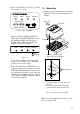
5. Press the [AUTO] and [+] keys together more than two seconds. AUTO TRUE CALIB STATUS Bow mark PG-1000 Figure 5 Key and LEDs After the TRUE, CALIB and STATUS LEDs light and AUTO LED blinks, rotate the equipment 360º slowly, keeping it uplight. If three LEDs are lighting, the mounting location is suitable. ; ; 1. Fix the sensor by using screws and washers (supplied). The size of the fixing hole is ø 4.5 mm. TRUE INTEGRATED HEADING SENSOR AUTO Mounting Ship's bow CALIBRATION AUTO 1.
Checking for inclination Make sure that the PG-1000 is mounted horizontally by the following checks. BOW 12-24 VDC + - AD10 NMEA 1. Press the [TRUE] and [+] keys more than two seconds. Grounding When the inclination is within ±5°, STATUS LED lights and TRUE LED blinks. AUTO ;; ;; TRUE CALIB Ground terminal STATUS 12-24 VDC ;; : On : Blinking : Off Heading data External equipment (Radar, ARPA, Autopilot, etc.
1.5 Correcting Magnetic Field Distortion (Deviation) The magnetic field at the sensor around ship is subjects to change with the ship structure, engins, electronic equipment or any ferrous materials in the vicinity. The PG-1000 contains an automatic correction facility against magnetic field distortion aboard the ship. 1. Do this procedure in a calm water. 2. Steer the boat clockwise or counterclockwise in a circular course. Take more than two minutes to complete the circle (at about 3 kt).
Results of correction Causes AUTO TRUE CALIB STATUS ;; ;; Above range of magnetic sensor ;; ;; ;; Magnetic field distortion Turning error Remedy Follow the procedure in above from step 2 after the replacement of unit. Follow the procedure in above from step 2 after the replacement of unit. ;; ; ;; ;; ;; Follow the procedure in above from step 2. : On : Blinking Figure 13 Note: Correction can also be done at Remote Display DD-2000. See the Operator's Manual for the DC-2000. 2.
3. Press the [+] or [-] key to change interval. 4. Press the [AUTO] and [TRUE] keys together more than two seconds to return to the normal mode. The STATUS LED blinks while the equipment is being calibrated and lights when the calibration is completed (return to normal mode). Do not operate the equipment while the LED is blinking; calibration will be incomplete. 4. Press the [AUTO] and [TRUE] keys together more than two seconds to return to the normal mode.
2 CORRECTING MAGNETIC ANOMALIES 2.1 Controls and Indications 2.2 Turning the Power On/Off Note: You may leave port after the STATUS On: Auto correction is on. LED begins lighting (not blinking). Off: Auto correction is off. On: True heading is output. Off: Magnetic heading is output. Power to the sensor unit may be turned on or Off: Normal Blinking: Correcting the deviation. (On installing.) On: Normal Off: Error off at the mains switchboard. 1. Turn the mains switch on. STATUS LED blinks.
2.3 Automatic Distortion Compensation Magnetic field distortion can be automatically corrected as follows: Note: This function is only effective after correcting for magnetic field distortion (refer to page 5). 1. Press the [AUTO] key more than two seconds to light the AUTO LED. AUTO TRUE CALIB STATUS RMC or VTG data is required which contains GPS position in RMC, SOG (speed over ground) and COG (course over ground) in VTG. 2. Set up magnetic variation (manual or automatic) at the GPS navigator. 3.
3 MAINTENANCE & TROUBLESHOOTING 3.1 Maintenance Regular maintenance is important to maintain intended performance over a long period. Regularly check the following: • Clean the component with a soft cloth. Do not use chemical cleaners; they can remove paint and markings. • Make sure all connections are tight. • Check the ground terminal for corrosion. Clean if necessary. 3.2 Troubleshooting The table below provides simple troubleshooting procedures which the user can follow to restore normal operation.
3.3 Diagnostic test The PG-1000 has a self-test which checks the circuit board and keys for proper operation. LED/KEY/ROM/RAM test 1. Disconnect the power cable from the equipment. 2. While pressing the [AUTO] key, reattach the power cable. The test sequence is as below. AUTO TRUE CALIB STATUS 5. Press the [AUTO] and [TRUE] keys together more than two seconds to escape from the test.
4. Disconnect the power cable off from the equipment, and then reattach it. 5. Mount the equipment at the previous position, referring to page 3. 3.4 Displaying Program Version No. When the equipment is powered on, the program no., denoted by LEDs in binary notation, is shown about 1 second. For example, LED state shown below means the program no. is 5. AUTO TRUE CALIB 8 4 2 STATUS 1 : On : Off Figure 24 LED state and program version no.
PARTS LOCATION AND LIST C PU Board PG-1000, cover opened Name CPU Board Type 64P1135 Code No.