Back MULTI-PURPOSE LCD DISPLAY MU-150C
SAFETY INSTRUCTIONS Safety Instructions for the Operator Safety Instructions for the Installer WARNING WARNING Do not open the equipment. Do not open the cover unless totally familiar with electrical circuits and service manual. Only qualified personnel should work inside the equipment. Improper handling can result in electrical shock. Do not disassemble or modify the equipment. Fire, electrical shock or serious injury can result.
TABLE OF CONTENTS FOREWORD ........................................................................................................ iii SYSTEM CONFIGURATION................................................................................ iv EQUIPMENT LISTS .............................................................................................. v 1 MOUNTING ...................................................................................................... 1 1.1 Display Unit ..........................
FOREWORD A Word to the Owner of the MU-150C FURUNO Electric Company thanks you for purchasing the MU-150C 15” Multi-Purpose LCD Display. We are confident you will discover why the FURUNO name has become synonymous with quality and reliability. For over 50 years FURUNO Electric Company has enjoyed an enviable reputation for quality and reliability throughout the world. This dedication to excellence is furthered by our extensive global network of agents and dealers.
SYSTEM CONFIGURATION RGB Radar, Video Plotter, Navigator, Video Sounder, Scanning Sonar, etc. 24 VDC or 100 - 240 VAC Control unit of Video Sounder (e.g., FCV-1200 series) NMEA 0183 Navigator (GPS, etc.)* * = When using the FCV-1200 series or CH-250, NMEA 0183 data may be output to the MU-150C instead of the interface unit.
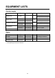
EQUIPMENT LISTS Standard supply Name Display Unit Spare Parts * Installation Materials * Accessories * Bracket * Type Code No. Qty − 1 MU-150C Remarks AC specification DC specification For DC SP10-02801 001-414-460 SP10-02802 001-414-970 CP10-04910 001-414-690 CP10-04920 001-414-700 FP10-02501 001-414-490 1 set FP10-05401 001-402-540 1 For FCV-1500L FP10-02510 001-414-510 1 Including FP10-02511 Code No.
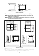
1 MOUNTING Refer to the outline drawing at the end of the manual for mounting dimensions. Note: The LCD is made of glass. Handle it with care. 1.1 Display Unit The display unit may be flush mounted in a panel or on a desktop, using the optional bracket. Display tilt can be chosen from 9° or 20°, by the location of the mounting plate. When selecting a mounting location, keep in mind the following points: • Locate the unit out of direct sunlight.
See Note 2. Cover Display Unit Display unit and cover 3. Fasten the display unit to the mounting location with six tapping screws (5X30). Note 1: Hex head bolts may also be used to fasten the display unit. However, their length must be at least 30 mm. Note 2: Use M5 bolt or tapping screw (nominal diameter: M5), although the size of the mounting holes in the display unit is M8. 384 ±0.5 333 ±0.5 366 ±1 315 ±1 15 ±0.5 100 333 ±0.5 315 ±1 384 ±0.5 82 366 ±1 45 15 ±0.5 259 ±0.5 259 ±0.
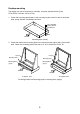
Desktop mounting The display unit can be mounted on a desktop, using the optional bracket (Type: FP10-02510, Code No.: 001-414-510). 1. Fasten the mounting base (lower) to the mounting location with four sets of hex head bolts, spring washers, flat washers and nuts. Hex Head Bolt Spring Washer Flat Washer Nut FRONT Mounting base (lower) 2. Fasten the bracket and mounting plate to the mounting base (upper) with 12 hex head bolts.
3. Loosely screw six screws (M5X15) into the holes at the rear of the display unit. Set the screws on the display unit to the holes on the bracket and then tighten the screws. (Note that the display unit may also be mounted in portrait orientation.) Fastening the front panel 4. Fasten the power cable (local supply in case of AC power), cable from the control and operation sections of external equipment and ground wire (local supply) at the rear of the MU-150C.
5. Grease the two hex head bolts for fastening the display unit to the mounting base (lower). 6. Fasten the display unit to the mounting base (lower) with the two hex head bolts greased at step 5. Hex Head Bolt Fastening the mounting base (lower) to the display unit 7. For portrait orientation, attach logo (supplied) at upper left hand corner.
1.1.1 Hood (option) A hood (portrait or landscape) is optionally available. Attach it to the display unit with Velcro tape as shown below. 1. Attach nine sets of Velcro tape to the display unit at the locations shown below, in as straight as possible. Attach in line. Attach in line. Display unit, how to attach Velcro tapes 2. Attach the hood to the display unit.
2 WIRING 2.1 Wiring External Equipment Connect external equipment to the MU-150C by referring to the drawings in this section. A cable with connector at both ends is provided to connect equipment. General-purpose monitor To use the MU-150C as a general-purpose monitor, connect equipment with a mini D-SUB 15P connector. In this case do not connect a navigator to the NMEA port. Nav data is output through the D-SUB 25P connector.
Connecting FCV-1200 series and CH-250 Using the cables designated below (or equivalent) to connect the FCV-1200 series or CH-250 makes their interface unit of the FCV-1200 series and CH-250 unnecessary. The mini D-SUB 15 P connector cannot be used to connect the FCV-1200 series and CH-250. Navigator, etc.
• Cable 06S4078 is of waterproof construction, however, the MU-150C is not waterproof (specification IPX0). Therefore, remove rubber cover and fixing metal from the display side of the cable. Remove fixing metal. Remove rubber cover.
3 ADJUSTMENTS Controls for adjustment of the picture are provided on the rear of the display unit. Open the small cover to access the controls.
3.1 Picture Adjustment Contrast and picture are adjusted with [S1]: Opens menu; selects menu items. [S2]: Increases setting. [S3]: Decreases setting. [S4]: Initializes setting. Note: Though “EXIT” is printed on the CONE Board (10P6877), the function of S4 switch is “RESET.” [S1] Brilliance (Not used.
3.2 RGB Adjustment Color may be adjusted with the following potentiometers. Turn the potentiometers clockwise to increase color. Model FCV-1200 Series, CH-250, FR-1760DS GD/GP-280/380/680, FCV-1500 Series, CH-37, CSH23/73/83, FR-1500 MK3 Series Potentiometer Setting Default setting Fully clockwise R1: Red R2: Green R3: Blue 3.3 Brilliance Adjustment Brilliance can be adjusted from the control unit of the FCV-1200 series or CH-250 by setting jumper block J17 as below.
4 OPERATION FURUNO LED BRILLIANCE Control POWER Switch Display unit POWER switch: Turns the power on/off. The LED lamp lights in green when the unit is turned on and goes off when the unit is turned off. To turn the MU-150C on and off from the control unit of a video sounder such as the FCV-1200 series, turn on the POWER switch of the MU-150C. Note that with the MU-150C turned on and the FCV-1200 turned off the LED on the MU-150C lights in red. This means that weak current is flowing to the MU-150C.
5 MAINTENANCE, TROUBLESHOOTING WARNING ELECTRICAL SHOCK HAZARD Do not open the equipment. Only qualified personnel should work inside the equipment. 5.1 Maintenance Routine maintenance Regular maintenance is important for good performance. Check the following on a regular basis to keep the equipment in good operating condition. • Check that the connectors at the rear of the display unit are tightly fastened. • Check the ground wire and ground terminal for rust. Clean if necessary.
5.2 Troubleshooting The table below provides troubleshooting procedures to use when no picture appears. If you cannot restore the picture, do not attempt to check inside the equipment – there are no user serviceable parts inside. Refer any work to a qualified technician. Troubleshooting table Reason for no picture Remedy Battery voltage too high. Check battery voltage. Fuse has blown. Replace fuse. Cable between MU-150C and external equipment has loosened. Refasten cable. Power cable has loosened.
APPENDIX Modification for Switching from Landscape to Portrait Orientation To use the MU-150C for portrait with the CH-37, FCV-1200 series, FCV-1500 series or FR-1760DS, the LCD assembly must be turned 180°. 1. Place the display unit on a workbench with the LCD side down. It is recommended to place the unit on cushioning material so as not to place pressure on knob. 2.
4. Referring to the arrows in the figure below for location, disconnect the connector and four power switch tag terminals and release cable from CK clamp. Note: When disconnecting the tag terminals, pull them by the metal part of the terminal. Do not disconnect by pulling the cable – cables may become separated from the terminal. Power assy.
5. Unfasten the eight screws marked with the arrows in the figure below. Display unit, rear view 6. Release the cable from the clamp marked with the gray arrow in the figure above. 7. Turn the LCD assembly 180°. POWER chassis Display unit, rear view 8. Fasten screws unfastened at step 5. (Torque: 0.39 ±0.04 Nm; 4 ±0.4 kgm) 9. Turn the power chassis 180° counterclockwise, making sure no load is placed on the cable at the center of the power chassis when turning.
11. Fasten cables with the clamps marked with the white arrows in the figure below. Connect the power connector to J1 on the pcb 10P3879 as follows: 1, Brown; 3, Orange; 4, Purple, 6, White. Location of power switch and pcb 10P3879 12. Fix the rear cover with 14 screws (M4 x 8). (Torque 1.47 ±0.15 Nm; 15 ±1.5 kgm) 13. Temporarily fasten the cover for the power section and connectors with 10 screws (M3 x 8). 14. Fix four spacers for connectors. (Torque: 0.39 ±0.04 Nm; 4 ±0.4 kgm) 15.
SPECIFICATIONS OF MULTI-PURPOSE LCD DISPLAY MU-150C 1 GENERAL 1.1 Display 15.0 inch color LCD, 304.1 x 228.1 mm 1.2 Brightness 180 cd/m2 typical, 150 cd/m2 minimum 1.3 Resolution VGA (640 x 480), XGA (1024 x 768) 1.4 Viewing Angle 160° (left/right: 80°, up/down: 80°) 1.5 Input Signal RGB: 0.7 Vp-p to 3.0 Vp-p, Synchronization: TTL level 2 POWER SUPPLY 2.1 Rated Voltage 100-240 VAC: 0.7-0.4 A, 1 phase, 50-60 Hz 24 VDC, 1.4 A 3 ENVIRONMENTAL CONDITIO N 3.
This page is intentionally left blank.
A-1 PACKING LIST 10CQ-X-9851 -5 1/1 MU-150C-H-DC-CS N A M E ユニット O U T L I N E DESCRIPTION/CODE № Q'TY UNIT MU-150C-H-DC 15型カラーLCD表示器 1 MULTI-PURPOSE LCD DISPLAY 000-012-618 予備品 SPARE PARTS SP10-02801 FGMB 3A 125V ヒューズ 2 FUSE 000-104-909 付属品 ACCESSORIES FP10-02501 10-075-1052-0 ロゴシート 1 LOGO SEAL 100-294-900 工事材料 INSTALLATION MATERIALS CP10-04902 MJ-A3SPF0020-050Z ケーブル組品MJ 1 CABLE ASSY.
A - 1A A-1A PACKING LIST 10CQ-X-9855 -1 1/1 MU-150C-H-AC-CS N A M E ユニット O U T L I N E DESCRIPTION/CODE № Q'TY UNIT MU-150C-H-AC 15型カラーLCD表示器 1 MULTI-PURPOSE LCD DISPLAY 000-012-617 予備品 SPARE PARTS SP10-02802 FGMB 1.
A-2
Your Local Agent/Dealer 9-52 Ashihara-cho, Nishinomiya 662-8580, JAPAN Telephone : 0798-65-2111 Fax 0798-65-4200 : All rights reserved. Printed in Japan FIRST EDITION : JAN JAN.. 2002 C3 Pub. No. OME-20250 ( YOTA ) MU-150C : OCT. OCT.