USER MANUAL Series X - Maritime Multi Display (MMD) Models HD 12T21 MMD-xxx-Fxxx - 12.1 inch Maritime Multi Display HD 15T21 MMD-xxx-Fxxx - 15.0 inch Maritime Multi Display HD 17T21 MMD-xxx-Fxxx - 17.0 inch Maritime Multi Display HD 19T21 MMD-xxx-Fxxx - 19.0 inch Maritime Multi Display HD 24T21 MMD-xxx-Fxxx - 24.0 inch Maritime Multi Display HD 26T21 MMD-xxx-Fxxx - 25.
Copyright © 2013 Hatteland Display AS Aamsosen, N-5578 Nedre Vats, Norway. All rights are reserved by Hatteland Display AS. This information may not, in whole or in part, be copied, photocopied, reproduced, translated or reduced to any electronic medium or machinereadable form without the prior written consent of Hatteland Display AS. Review also: www.hatteland-display.com/pdf/misc/doc100703-1_permission_to_create_user_manuals.
Contents Contents........................................................................................... 3 Contents of package...................................................................................6 General............................................................................................. 7 About this manual.......................................................................................8 About Hatteland Display................................................................
Contents Operation........................................................................................ 39 User Controls............................................................................................40 On Screen Display (OSD) Menu Introduction...........................................42 OSD Keycode / OSD Lock Mode..............................................................42 OSD Simplified and Full Menu modes (examples)...................................43 OSD Visual Feedback (examples)..
Contents Technical Drawings - Accessories............................................... 87 Technical Drawings - HD CMB SX1-A1....................................................88 Console Mount Kit 12”,15”,17”,19”................................................................. 88 Technical Drawings - HD CMB SX1-B1....................................................89 Console Mount Kit 24”................................................................................... 89 Console Mounting 24”...........
Contents of package Note: Entries listed below are for Standard factory shipments. Customized factory shipments may deviate from this list. Item Description 1 pcs of Standard DVI Signal Cable. DVI-D 18+1P Male to DVI-D 18+1P Male Single Link - Length 2.0m Illustration HA-SDM-2M 1 pcs of Standard VGA Signal Cable. DSUB 15P Male to DSUB 15P Male - Length 2.0m HA-VGA-2M-32 1 pcs of power cable European Type F “Schuko” to IEC. Length 1.
General 7
Hatteland Display AS About this manual The manual contains electrical, mechanical and input/output signal specifications. All specifications in this manual, due to manufacturing, new revisions and approvals, are subject to change without notice. However, the last update and revision of this manual are shown both on the frontpage and also in the “Revision History” chapter at the end of the manual.
Displays Series X Maritime Multi Display (MMD) - Introduction As a leading manufacturer of display and computer hardware for the maritime segment, Hatteland Display continuously gauges and responds to market needs. Our commitment to develop specialized products for a multitude of onboard ship systems continues, and with that the introduction now of a brand new product range called, Series X.
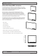
Product Labeling Introduction This section details the locations, content details and specifications for factory mounted labels for all currently available standard Hatteland Display Maritime Multi Display (MMD) models. This information will in most cases also apply for most Customized Models as well, but may differ based on customer requirements, in that case, please refer to the customized User Manual (paper or electronic version, dependent on customer requirements).
Product Labeling Label Locations Number ID and coloring based on “Label Size and Types“ table from previous page. All illustrations below is seen from rear (and side where needed) with connectors facing down. Actual labels regarding its size and text orientation vs product size is drawn in. Due to space restrictions on selected units, some labels will be rotated 90 degrees to fit properly.
Product Labeling Warranty label covers screw. Labels placed on rear. HD 19T21 MMD-xxx-Fxxx Warranty label covers screw. Labels placed on rear. HD 24T21 MMD-xxx-Fxxx Warranty label covers screw. Labels placed on rear.
Product Labeling Warranty Label If you are to perform service on a unit still under warranty, any warranty will be void if this label show signs of removal attempts (re-gluing) or removed completely. This label is located on the back of the product and covers a key screw. This is to aid service departments to determine if there has been any unauthorized service on a unit still under warranty.
Touch screen products Introduction to products with touch screen Nearly all of our Series X products with touch screen uses Projected Capacitive Touch screen (PCTS), widely used with great success on mobile phones and typical pad devices. PCTS can be equally effective also for marine applications. One of the advantages of PCTS is that it has features seen in both resistive and surface capacitive touch screen technologies.
Touch screen products Touch Screen Drivers and Documentation All units are shipped with a Documentation and Drivers DVD or CD which contains suitable drivers* for touch screens. (Named MEDIA STD01). You can also visit our website www.hatteland-display.com to view the same list (or even recently new added products) for our models with touch screen. Before using the touch screen, it should be calibrated for your system. Please install the 3rd party software* and use the Calibrate function.
This page left intentionally blank 16
Installation 17
General Installation Recommendations First Things First! ATTENTION! IND100148-5 - Rev 02 To prevent damage to chassis and glass, please review the illustrations below before handling units. CORRECT WRONG HANDLING ! HANDLING ! Place horizontally on a smooth and clean surface Do not stress the corners, nor place it on a coarse and/or dirty surface Place horizontally on a smooth and clean surface Do not stress the corners, nor place it on a coarse and/or dirty surface Installation and mounting 1.
General Installation Recommendations 7. If the push buttons of the product are not illuminated, an external, dimmable illumination (IEC 60945 Ed. 4, 4.2.2.3, e.g. Goose neck light) is required for navigational use. The illumination shall be dazzle-free and adjustable to extinction. 8. Information about necessary pull-relievers for cables is indicated in the Physical Connection section of this manual. Attention must be paid to this information so that cable breaks will not occur, e.g. during service work. 9.
General Installation Recommendations D: General rule for console mounted units: To ensure proper cooling airflow, long-life and stable operation for all units, please make sure that the console casing have either fans or decent ventilation holes to prevent overheating inside the console due to the combined temperature of both Display or Panel Computer units together with other electronic instruments.
General Installation Recommendations Ergonomics 1. The front surface of the display glass has an anti-reflective (AR) coating which can be scratched and damaged with improper cleaning. It is recommended to use only 90+% pure Isopropyl alcohol (Isopropanol) and a soft fabric cloth for this first cleaning. Fold a cloth into a small pad, dampen the cloth with alcohol, and wipe the glass from one edge to the other in one direction with one continuous motion. The product glass will require cleaning as needed.
General Installation Recommendations Maximum Cable Length Any cable should generally be kept as short as possible to provide a high quality input/output. The maximum signal cable length will depend on the signal resolution and frequency, but also on the quality of the signal output from the computer/radar.
General Installation Recommendations Housing / Terminal Block Connector Overview Housing / Terminal Block connectors are available in different sizes (2-pin, 4-pin, 5-pin) which plugs into the connector area of the unit. They are mounted by factory default and delivered with the unit. The housing / terminal block connectors have steering rails, which ensures that it can not be mounted wrong. The color of these connectors may vary between black, green and orange depending on manufacturer.
General Installation Recommendations Configuring Housing / Terminal Block connectors Below is a brief illustration that might be useful during configuration and installation of such connectors. You will need suitable pre-configured cable(s) and tools to configure the connector(s) and cable(s) that are present in your installation environment. Below is a sample procedure for a 2-pin DC power connector. The procedure is the same for other connectors of this type as listed in table above.
Installation Procedures Panel / Console Mounting Key Hole Bracket Kit for 12”,15”,17”,19” You need: Allen Wrench tool (3mm), 4 pcs of HD CMB SX1-A1 kit (included in delivery). Procedure suitable for: Display and Panel Computers Series X range. Attention: A suitable pre-cut panel cutout should be made prior to mounting. Do not force the unit into the panel cutout as it might break the outer glass or scratch the chassis on the unit. Make sure that the panel cutout is not too tight for the unit.
Installation Procedures Panel Cutout / Console Mounting Bracket Kit for 24”,26” You need: Pozidriv tool, 1 pcs of HD CMB SX1-B1 kit (included in delivery). Procedure suitable for: Display and Panel Computers Series X range. 24 inch used as illustration below, but same procedure also valid for 26 inch models. Attention: A suitable pre-cut panel cutout should be made prior to mounting. Do not force the unit into the panel cutout as it might break the outer glass or scratch the chassis on the unit.
Installation Procedures Mounting Bracket, Table / Desktop / Ceiling - 12”,15”,17”,19” Procedure suitable for: Display (MMD/STD) and Panel Computer (MMC) Series X product ranges. Two versions of bracket exists, please review the table below to identify your unit model and bracket type. Brackets that are currently sold/delivered are marked with green color. Those which are obsolete (and replaced by newer type of bracket) are shown in red color.
Installation Procedures HD TMB-SX1-A1 HD TMB-SX1-B1 HD 12T21 MMD-xxx-Fxxx HD 12T21 STD-xxx-Fxxx HD 12T21 MMC-xxx-xxxx HD 15T21 MMD-xxx-Fxxx HD 15T21 STD-xxx-Fxxx HD 15T21 MMC-xxx-xxxx “HW01”: Sold since April 2012. Fits Double Key Hole Chassis only. HD 17T21 MMD-xxx-Fxxx HD 17T21 STD-xxx-Fxxx HD 17T21 MxC-xxx-xxxx HD 19T21 MMD-xxx-Fxxx HD 19T21 STD-xxx-Fxxx HD 19T21 MxC-xxx-xxxx “HW01”: Sold since May 2012. Fits Double Key Hole Chassis only. EN60945 Tested. EN60945 Tested.
Installation Procedures Important to know about LEFT and RIGHT brackets Throughout the following installation procedure for both BRD and TMB brackets, it is important to understand the difference between LEFT and RIGHT brackets. The Display and Panel Computer chassis are not 100% square boxed, but are slightly designed with a minor narrow angled chassis towards the rear (FIG1) to allow easier “dropin” of units into consoles.
Installation Procedures Installation Procedure - BRD Versions Procedure suitable for: Display (MMD/STD) and Panel Computer (MMC) Series X product ranges. You need: - M4, M5 Unbrako® Hex Key tool (not included with delivery). - Fasteners (6 pcs M6) for mounting complete unit onto table or desktop location (not included with delivery). - 1 pcs of HD xxBRD SX1-A1 Mounting Bracket Kit, where xx=15, 17 or 19 inch.
Installation Procedures ▼ 5: Ensure that both Key Hole Plugs slide into the Key Holes and goes to the bottom position (FIG1 and FIG2). If they appear too tight, you may loose the Key Hole Plug screw a few turns and re-try (see previous step 2). FIG3 shows Key Hole Plug correctly into Key Hole and both brackets in place. FIG2 FIG3 FIG1 FIG3 ▼ 6: Tighten Key Hole Screw firmly on each side and make sure the brackets are properly mounted and aligned to the main chassis of unit.
Installation Procedures Installation Procedure - TMB Versions Procedure suitable for: Display (MMD/STD) and Panel Computer (MMC) Series X product ranges. You need: - M4 Unbrako® Hex Key tool (not included with delivery). - Fasteners (6 pcs M6) for mounting complete unit onto table or desktop location (not included with delivery).
Installation Procedures ▼ 5: While unit is lying flat on table, check the Tilting Lock Pin position. These can be pulled out by hand, turned 90° (FIG1) and turned back 90° until the Lock Pin automatically clicks into place by a spring (FIG2). FIG2 Glass Facing Up FIG1 Locked Unlocked ▼ 6: You may now mount the unit onto your desired location.
Installation Procedures Mounting Bracket for Table / Desktop installation - 24”,26” You need: M5, M10 Unbrako® Hex Key tool, M10 Wrench and 1 pcs of HD TMB SX1-C1 Mounting Bracket Kit. Fasteners (6 pcs M6) for Table / Desktop location not included. Procedure suitable for: Display and Panel Computers. Attention: A suitable pre-drilled location and knowledge of measurements for both main unit and brackets/tilting functionality should be prepared and checked prior to mounting.
Physical Connections Connection area of unit (illustration) 3 x BNC, Composite Video IN USB Touch RJ45 Network 2 x DVI-D In RS-422/RS-485 COM RS-232 COM 2 x VGA/RGB In VGA/RGB Out Power Input AC Grounding Screw Potmeter Port Power Input DC Note: 19 inch unit used as example above, please review specifications for your actual model. Reduce Cable Tension To reduce tension of the cables you connect, secure them with a cable tie to the available chassis hinges located near the connectors.
Physical Connections DVI-D IN: Connect your DVI cable to any of the two DVI-D 18+1P, Single Link Connector (female). Secure your DVI cable to the hex spacers provided on the unit and make sure you do not bend any of the pins inside the connector. Connect the other end of the cable to the DVI connector on your equipment and secure it.
Physical Connections POWER INPUT: The internal AC power module supports both 115VAC/60Hz and 230VAC/50Hz power input. Please check specifications for your unit. - + POWER INPUT: Connect your DC power cable to the 2-pin Terminal Block 5.08 connector. The internal DC power module supports 24VDC. For more information, please review “Housing Connector Overview” earlier in this manual.
This page left intentionally blank 38
Operation 39
User Controls USER CONTROLS OVERVIEW The units are designed by using Glass Display Control™ (GDC) touch technology to allow interactivity adjusting brilliance (brightness) and control power on / off with the use of illuminated symbols. Note that these symbols are only visible (backlight illuminated) when suitable power is connected.
User Controls SERVICE Action Indicators: = Built in functionality to determine when the unit requires service in order to perform within preset factory standards. This area will illuminate constantly until the unit is powered off. Note that by touching this symbol no action will be performed or has been assigned. Brightness Adjust: Brilliance / Brightness adjustment of the displayed image is adjusted by touching the (-) or (+) illuminated symbols.
OSD Menu Overview On Screen Display (OSD) Menu Introduction The OSD menu consists of main menus and submenus which is very easy to navigate through. All functions are explained in-depth later in this user manual. You should prior to using the OSD menu and functions, be sure to familiarize yourself with how to physically access the menu, how to navigate up/down/left/right, how to modify values, exiting menus and more.
OSD Menu Overview OSD Simplified and Full Menu modes (examples) You may encounter two different menu size setups based on factory default or by customized preset configuration. The Simplified Menu mode offers easy and clear access to most commonly used functions. The Full Menu mode offers a more advanced menu with technical information and is suited for more technical minded users.
OSD Menu Overview OSD Menu Structure In this table all functions within menus and their submenus are shown. Functions that begins with an asterix (*) and in bold/red font color style indicates this function/menu is only available during “Full” menu mode or during Video CVBS fullscreen. Functions with a “>” in the end, indicates a submenu or list of options will be displayed. Depth of the submenus (levels) are identified from 1 to 5.
OSD Menu Overview Color Mode Settings (page 49) Level 1 (Main Menu) Level 2 Color Mode Settings > < Exit Color Temperature > 9300K, 8000K, 6500K > User > *Gamma > Level 3 No Calibration, Calibration VGA, Calibration DVI Level 4 Level 5 (Automatic Action) < Exit Red > Green > Blue > (Slider Bar) (Slider Bar) (Slider Bar) Level 4 Level 5 Multi-PIP Settings (page 50-51) Level 1 (Main Menu) Level 2 Multi-PIP Settings > < Exit PIP Mode > PIP Display > Level 3 PIP Off, PIP Child, PIP Split, PIP W
OSD Menu Overview OSD Settings (page 52-55) Level 1 (Main Menu) Level 2 OSD Settings > < Exit OSD Position > Language > Presets > Level 3 Level 4 < Exit OSD H Position > OSD V Position > < Exit Norsk > English > Français > Deutsch > Italiano > Español > 日本語 > 簡體中文 > < Exit Recall > Save > Load > OSD Timeout (Sec) > OSD Transparent > OSD Mode > (Slider Bar) (Slider Bar) < Exit Simplified > Full > OSD Lock Mode > Normal Mode > Password Protect > Full Mode > OSD Key Outdoor > Hot Key Assignment >
OSD Menu Overview Management Settings (page 56-61) Level 1 (Main Menu) Level 2 Level 3 Management Settings > < Exit * Graphic Scaling > Level 4 < Exit Graphic Scaling > Zoom > Horizont Stretch > Vertical Stretch > Auto Adjustment > On, Off *Unknown Timing Search > < Exit Auto Mode > Blind Mode > Save Timing > Clear Timing > (Slider Bar) (Slider Bar) On, Off Enable, Disable Enable, Disable < Exit RS232 > 2-wire RS-485 > 4-wire RS485/422 > Address RS > IP Address > LED Drive > *GDC Sensitivity > *Fil
OSD Menu Functions On Screen Display (OSD) Menu Functions The following section covers all possible settings that the user can (in a certain mode) encounter or needs to adjust via easy understandable menus, text and navigation. For simpler reading the menu choice “Exit” has been left out of description in this chapter intentionally. Whenever “Exit” is available, you can exit current menu and go back to the previous one visited.
OSD Menu Functions Input Source Settings - Rename Source |---2--- By factory default, every signal source input are named based on it’s signal property as described in the previous functions, but with the rename source function you can rename these into more understandable descriptions like; “FRONT-CAMERA”, “NIGHT RADAR” etc. When activated, a requester on screen similar to a standard keyboard layout will appear.
OSD Menu Functions Image Settings Lets you configure various visual preferences for any signal. The contents of these submenu are listed below. Image Settings - Auto Position |---2--- Will automatically fit the current displayed full screen signal and center it based on the active area of the TFT display. This function rely on properties of the incoming signal.
OSD Menu Functions Image Settings - Hue *Available in “Full Mode” only + Video Fullscreen |---2--- Allows to adjust/shift the main color properties of all Red, Green, Blue and Yellow (unique hues) values. This can be useful for certain Composite Video sources (no effect on DVI/VGA signals) whose output may have shifted or seems to be “out of phase”, where for instance blue seems more dominant than green, red and yellow-ish colors.
OSD Menu Functions Image Settings - Display - Clock |--------3-------- Adjust the horizontal frequency (clock) of the analog signal to improve visibility of the entire image. When it is adjusted, you will notice that the image will appear to be stretched and might in some situations start to flicker/scroll, at which point you must reverse the last adjustment to stop it from flickering/scrolling anymore.
OSD Menu Functions Image Settings - Video Setup *Available when Video Fullscreen only |---2--- Provides submenus where the following settings for Composite video signals are available: Image Settings - Video Setup - Main MADI mode |--------3-------- Motion Adaptive De-Interlacing. Motion adaptive de-interlacing is a pixel-based two-phase process. Phase 1 involves the detection of motion and the generation of a motion value for each pixel.
OSD Menu Functions Image Settings - Video Setup - Noise Reduction - MPEG NR Mode |-------------4------------- MPEG NR (the generic coding of moving pictures and associated audio information) can be set to either “ON” or “OFF”. This function will try to reduce noise as result from compressed/formatted MPEG video streams.
OSD Menu Functions Color Mode Settings Lets you adjust the color temperature (Kelvin degrees) of the image. This applies to the Main Source signal. Window overlays (PIP/PBP) and the OSD Menu overlay will be unaffected. Lower values make the image appear warmer, while higher values will make it appear cooler. The contents of these submenus are listed below.
OSD Menu Functions Multi-PIP Settings Lets you adjust how the Picture-in-Picture (PIP) or Picture-by-Picture (PBP) display mode is set up. The default position of the rectangle is set to upper left corner of the Active Display area. Note that this requires a valid incoming signal to be present in either the VGA or CVBS inputs. The contents of these submenus are listed below.
OSD Menu Functions Multi-PIP Settings - PIP Position |--------3-------- When PIP Child mode is active, the size and position of the frame displaying the Secondary Source can be adjusted by means of submenus for size and position respectively below. Settings as follows: “PIP H-Position” = Adjust the Horizontal (left/right) position for Secondary Source, values from 0 to 100.
OSD Menu Functions OSD Settings Allows you to customize the visual appearance of the On Screen Display (OSD) menu, such as; position, transparency, time-out, assign hot keys, define access modes and save, load and recall favourite settings and more. The contents of these submenus are listed below. OSD Settings - OSD Position |---2--- Settings as follows: “OSD H Position” “OSD V Position” = Place the OSD menu overlay Horizontally (left/right), values from 0 to 100.
OSD Menu Functions OSD Settings - Presets - Save |--------3-------- Allows to save current state of all function and values to user defined presets. The contents of the submenu is listed below. Settings as follows: “User 1” “User 2” “User 3” “User 4” “User 5” = Save all OSD settings to User 1 slot. = Save all OSD settings to User 2 slot. = Save all OSD settings to User 3 slot. = Save all OSD settings to User 4 slot. = Save all OSD settings to User 5 slot.
OSD Menu Functions OSD Settings - OSD Mode |---2--- Configuring the OSD Mode to show as simplified/most common functions or advanced (full) setup. Settings as follows: “Simplified” = A few functions is not visible/available in this state. For most uses this is the preferred setting and are safe for the display functionality and continuous trusted operation on the unit. “Full” = All functions and parameters is visible/available in this state.
OSD Menu Functions OSD Settings - OSD Key Outdoor |---2--- To prevent accidental activation of Glass Display Control™ (GDC) touch functions, you can add an extra layer of security on how “sensitve” the touch detection operates. This applies for “MENU”, “(-) Brilliance (+)” and “Power Off” functions. The OSD Key Outdoor function is especially effective if the unit is located in a outside environment where rain drops could potentionally trigger touch button functions.
OSD Menu Functions Management Settings Allows you to adjust overall settings for interaction/communication for the unit, such as scaling, zoom, timing of signals, adjust voltages for LED (which illuminate the front glass symbols), sensitivity for the touch control, VGA filter and Serial/Ethernet communication and more. The contents of these submenus are listed below.
OSD Menu Functions Management Settings - Graphic Scaling - Horizont Stretch |--------3-------- All stretching will performed from center of active display area and outwards in one direction. Settings as follows: “Horizont Stretch” = Zoom/stretch current full screen signal in Horizontal direction only (left and right). Values from 0 to 100. ● Note: Values under or over 50, may cause blurry and unfocused imagery, since it overrides the external signal’s 1.
OSD Menu Functions Management Settings - Unknown Timing Search *Available in “Full Mode” only |---2--- Use this if you are unable to find or detect the incoming full screen signal automatically (applies for Analog VGA and CVBS video signals only. A PIP or PBP configured signal is not supported). It may be a customized signal regarding resolution and refresh frequency.
OSD Menu Functions Management Settings - Unknown Timing Search - Save Timing |--------3-------- The current “Timing Table Data” that is currently visible in the “Blind Mode” or via the “Auto Mode” functions may now be saved to a user defined slot. Available save slots from 1 to 8. Saving “Time Table Data” may prove to be useful until the external equipment is either replaced or changed.
OSD Menu Functions Management Settings - Filter *Available in “Full Mode” only |---2--- Filter (applies for VGA1 signal input only) is a Signal Noise Reduction technique to enhance a possible weak or bad RGB/VGA signal. It will remove certain types of noise patterns typically apparent in close proximity of other electronic equipment with less or lack of proper shielding to prevent interference. Settings as follows: “Filter” = Set to either “ON” or “OFF”.
OSD Menu Functions Management Settings - Communication *Available in “Full Mode” only |---2--- The unit allows for remote control (adjust brightness for example) and/or accessing internal information about the unit such as typenumber, serial number and more. To setup this feature, you first need to configure the Serial or Ethernet protocol properly to match your external equipment specifications. The contents of the submenus is listed below.
OSD Menu Functions Service Will show various technical and unit related information, such as; Firmware versions, Elapsed Time, Internal Temperature, Fault Status and activation for the internal Test Pattern image useful for troubleshooting. Some of these functions are static information while others are accessible.
OSD Menu Functions Service - Test Pattern |---2--- Will show the internal test pattern with greyscales, colors and raster patterned boxes to check for deviations in the TFT panel/display controller behaviour. It is independent of any current resolution or specifications found in the signal inputs. The test pattern is generated internally in the display controller and is sent 1:1 directly to the TFT panel.
This page left intentionally blank 70
Specifications 71
Specifications - HD 12T21 MMD-xxx-Fxxx SPECIFICATIONS Note: All specifications are subject to change without prior notice! Please visit www.hatteland-display.com for the latest electronic version. All specifications are subject to change without prior notice! TFT Technology: Physical Considerations: • High Quality TFT with LED Backlight • 12.
Specifications - HD 15T21 MMD-xxx-Fxxx SPECIFICATIONS Note: All specifications are subject to change without prior notice! Please visit www.hatteland-display.com for the latest electronic version. All specifications are subject to change without prior notice! TFT Technology: Physical Considerations: • High Quality TFT with LED Backlight • 15.
Specifications - HD 17T21 MMD-xxx-Fxxx SPECIFICATIONS Note: All specifications are subject to change without prior notice! Please visit www.hatteland-display.com for the latest electronic version. All specifications are subject to change without prior notice! TFT Technology: Physical Considerations: • High Quality TFT with LED Backlight • 17.
Specifications - HD 19T21 MMD-xxx-Fxxx SPECIFICATIONS Note: All specifications are subject to change without prior notice! Please visit www.hatteland-display.com for the latest electronic version. All specifications are subject to change without prior notice! TFT Technology: Physical Considerations: • • • • • • • • High Quality TFT with LED Backlight 19.
Specifications - HD 24T21 MMD-xxx-Fxxx SPECIFICATIONS Note: All specifications are subject to change without prior notice! Please visit www.hatteland-display.com for the latest electronic version. All specifications are subject to change without prior notice! TFT Technology: Physical Considerations: • • • • • • • • High Quality TFT with LED Backlight 24.
Specifications - HD 26T21 MMD-xxx-Fxxx (LED/CCFL version) SPECIFICATIONS Note: All specifications are subject to change without prior notice! Please visit www.hatteland-display.com for the latest electronic version. All specifications are subject to change without prior notice! TFT Technology: Physical Considerations: • • • • • • • • High Quality TFT with LED or CCFL Backlight 25.
Specifications - HD 26T21 MMD-xxx-FxxC (LED/CCFL version) SPECIFICATIONS Note: All specifications are subject to change without prior notice! Please visit www.hatteland-display.com for the latest electronic version. All specifications are subject to change without prior notice! TFT Technology: Physical Considerations: • • • • • • • • High Quality TFT with CCFL Backlight 25.
Technical Drawings 79
Dimensions might be shown with or without decimals and indicated as mm [inches]. Tolerance on drawings is +/- 1mm. For accurate measurements, check relevant DWG file. TBD, DRAWINGS PENDING 80 IND100132-218 This document is the property of Hatteland Display AS. This document and any authorized reproduction thereof, must not be used in any way against the interest of Hatteland Display AS. Any authorized reproduction, in whole or in part, must include this legend. Hatteland Display Proprietary information.
This document is the property of Hatteland Display AS. This document and any authorized reproduction thereof, must not be used in any way against the interest of Hatteland Display AS. Any authorized reproduction, in whole or in part, must include this legend. Hatteland Display Proprietary information. Not to be distributed to any third party without written permission. Dimensions might be shown with or without decimals and indicated as mm [inches]. Tolerance on drawings is +/- 1mm.
This document is the property of Hatteland Display AS. This document and any authorized reproduction thereof, must not be used in any way against the interest of Hatteland Display AS. Any authorized reproduction, in whole or in part, must include this legend. Hatteland Display Proprietary information. Not to be distributed to any third party without written permission. Dimensions might be shown with or without decimals and indicated as mm [inches]. Tolerance on drawings is +/- 1mm.
This document is the property of Hatteland Display AS. This document and any authorized reproduction thereof, must not be used in any way against the interest of Hatteland Display AS. Any authorized reproduction, in whole or in part, must include this legend. Hatteland Display Proprietary information. Not to be distributed to any third party without written permission. Dimensions might be shown with or without decimals and indicated as mm [inches]. Tolerance on drawings is +/- 1mm.
This document is the property of Hatteland Display AS. This document and any authorized reproduction thereof, must not be used in any way against the interest of Hatteland Display AS. Any authorized reproduction, in whole or in part, must include this legend. Hatteland Display Proprietary information. Not to be distributed to any third party without written permission. Dimensions might be shown with or without decimals and indicated as mm [inches]. Tolerance on drawings is +/- 1mm.
This document is the property of Hatteland Display AS. This document and any authorized reproduction thereof, must not be used in any way against the interest of Hatteland Display AS. Any authorized reproduction, in whole or in part, must include this legend. Hatteland Display Proprietary information. Not to be distributed to any third party without written permission. Dimensions might be shown with or without decimals and indicated as mm [inches]. Tolerance on drawings is +/- 1mm.
This document is the property of Hatteland Display AS. This document and any authorized reproduction thereof, must not be used in any way against the interest of Hatteland Display AS. Any authorized reproduction, in whole or in part, must include this legend. Hatteland Display Proprietary information. Not to be distributed to any third party without written permission. Dimensions might be shown with or without decimals and indicated as mm [inches]. Tolerance on drawings is +/- 1mm.
Technical Drawings - Accessories 87
This document is the property of Hatteland Display AS. This document and any authorized reproduction thereof, must not be used in any way against the interest of Hatteland Display AS. Any authorized reproduction, in whole or in part, must include this legend. Hatteland Display Proprietary information. Not to be distributed to any third party without written permission. Dimensions might be shown with or without decimals and indicated as mm [inches]. Tolerance on drawings is +/- 1mm.
This document is the property of Hatteland Display AS. This document and any authorized reproduction thereof, must not be used in any way against the interest of Hatteland Display AS. Any authorized reproduction, in whole or in part, must include this legend. Hatteland Display Proprietary information. Not to be distributed to any third party without written permission. Dimensions might be shown with or without decimals and indicated as mm [inches]. Tolerance on drawings is +/- 1mm.
This document is the property of Hatteland Display AS. This document and any authorized reproduction thereof, must not be used in any way against the interest of Hatteland Display AS. Any authorized reproduction, in whole or in part, must include this legend. Hatteland Display Proprietary information. Not to be distributed to any third party without written permission. Dimensions might be shown with or without decimals and indicated as mm [inches]. Tolerance on drawings is +/- 1mm.
A 0,16 594,00 581,00 23,39 22,87 FRONT VIEW 3 4 x R 4,00 1 2 3 PANEL CUTOUT FOR HD 24T21 XXX-XXX-XXXX, FLUSH MOUNTING. A 4 x R 4,00 2 4 4 0,16 5 6,50 5 0,26 6 6 SIDE VIEW 7 Console thickness. 7 A-A (2 : 1) 8,00 8 8 10,00 0,39 0,31 0,63 10 0,16 9 7251 Mechanical Designer Hatteland Display AS Åmsosen N-5578 Nedre Vats 10 07-11-2011 Date: Max thickness for mounting the bracket. CL BACK VIEW Sunken face for Display.
This document is the property of Hatteland Display AS. This document and any authorized reproduction thereof, must not be used in any way against the interest of Hatteland Display AS. Any authorized reproduction, in whole or in part, must include this legend. Hatteland Display Proprietary information. Not to be distributed to any third party without written permission. Dimensions might be shown with or without decimals and indicated as mm [inches]. Tolerance on drawings is +/- 1mm.
Appendixes 93
Pinout Assignments ID’s (1,2,3,A,B,C) denotes where connector is (by factory default) or may be available (through factory customization). Note that some combinations may not be possible due to space restrictions. List also valid for customized models. All pin out assignments are seen from users Point of View (POV) while looking straight at the connector. Please review the dedicated datasheet or technical drawings for your actual unit to identify and determine the presence of desired connector.
Pinout Assignments Serial COM RS-232 non-isolated, 9-pin DSUB Female 1 5 2 Serial COM RS-485/RS-422, 9-pin DSUB Male “Full Duplex Mode* B 3 4 3 2 1 B 1 2 3 4 5 9 8 7 6 PIN 01 PIN 02 PIN 03 PIN 04 PIN 05 PIN 06 PIN 07 PIN 08 PIN 09 BUZ+ TxD RxD DTR GND DSR RTS CTS BUZ- Buzzer Control Positive* Transmit Data Receive Data Data Terminal Ready Ground Data Set Ready Request To Send Clear To Send Buzzer Control Negative* 6 7 PIN 01 TxD- Transmit Data Negative PIN 02 TxD+ Transmit Data Positive PIN 03
Pinout Assignments 18/24/24+5 pin DVI-D, DVI-I, Single Link, Dual Link Combined Female 1 2 3 A 1 2 3 4 5 6 7 8 9 10 11 12 13 14 15 16 Potmeter Control, 9-pin DSUB Male B 1 C1 C2 5 B 4 3 2 1 C5 9 8 7 6 17 18 19 20 21 22 23 24 C3 C4 PIN 01 PIN 02 PIN 03 PIN 04 PIN 05 PIN 06 PIN 07 PIN 08 PIN 09 PIN 10 PIN 11 PIN 12 PIN 13 PIN 14 PIN 15 PIN 16 PIN 17 PIN 18 PIN 19 PIN 20 PIN 21 PIN 22 PIN 23 PIN 24 PIN C1 PIN C2 PIN C3 PIN C4 PIN C5 T.M.D.S. Data2 - (Digital - RED link 1) T.M.D.S.
Pinout Assignments 8-pin Digital Output / Input Module “Solid State Relay” 3 10-pin Digital Output / Input & Serial Module “Mechanical Relay & COM (isolated RS-422/485)” 3 A X1 DIG OUT A 3 1 2 3 4 1 2 3 4 Pin 01 X1 - Out: 41 Out + Pin 02 X1 - Out: 42 Out COM (Common Center Pin 03 X1 - Out: 31 Terminal) * Pin 04 X1 - Out: 32 NC (Normally Closed)* * IEC 60950 Compliant, 48VDC X1 - In: 52 X1 - In: 53 X1 - In: 61 X1 - In: 62 +24VDC GND (Ground) +24VDC +Input 5-pin Digital Output Module “Safety S
Pinout Assignments Pin Assignments - 25-pin Female Parallel (Optional for selected computers) 3 C 13 12 11 10 9 8 7 6 5 4 3 2 1 25 24 23 22 21 20 19 18 17 16 15 14 Pin 01 Pin 02 Pin 03 Pin 04 Pin 05 Pin 06 Pin 07 Pin 08 Pin 09 Pin 10 Pin 11 Pin 12 Pin 13 Pin 14 Pin 15 Pin 16 Pin 17 Pin 18 Pin 19 Pin 20 Pin 21 Pin 22 Pin 23 Pin 24 Pin 25 STROBE DATA0 DATA1 DATA2 DATA3 DATA4 DATA5 DATA6 DATA7 ACK BUSY PE SELECT AUTO FEED ERR# INIT# SLIN# GND GND GND GND GND GND GND GND This signal indicates to the printe
Basic Trouble-shooting GENERAL ISSUES FOR TFT PANEL BASED PRODUCTS Note: Applies for a range of various products. This is only meant as a general guide. NO PICTURE / LED BEHAVIOUR: If there is no light at all in the LED at the FRONT, check power cables. If the LED in front is green then check if the brightness is set/adjusted to max brightness. Lack of image is most likely to be caused by incorrect connection, lack of power or wrong BIOS settings.
Declaration of Conformity We, manufacturer, Hatteland Display AS, Åmsosen, N-5578 Nedre Vats, Norway declare under our sole responsibility that the JH MMD, JH MMC, JH STD, JH MIL, HM NMD, HM MIL, HM CMD, HT STD, HD MMD, HM MMD, HT MMC and HD MMC product ranges is in conformity with the following standards in accordance with the EMC Directive. Low Voltage Directive 2006/95/EC EN 60950 EMC Directive 2004/108/EC EN 55022 Class A EN 55024 Signature:........................................................
Return Of Goods Information Return of goods: (Applies not to warranty/normal service/repair of products) Hatteland Display referenced as “manufacturer” in this document. Before returning goods, please contact your system supplier before sending anything directly to manufacturer. When you return products after loan, test, evaulation or products subject for credit, you must ensure that all accessories received from our warehouse is returned.
Terms Terms Of Sale And Delivery 1) APPLICATION The terms of sale and delivery apply for Hatteland Display. 2) PRICE a) The price is per each, if nothing else has been stated, VAT not included. Price is based on the prices from our suppliers, current custom rates, taxes, rate of exchange and international raw material prices. We reserve ourselves the rights to adjustments in case of alternation on the above mentioned. b) Included in the price is the supplier’s standard packing.
Terms 12) CANCELLATION / RETURN Binding sales contract is concluded when we have confirmed customer’s purchase order. Any disagreements in our order confirmation must be reported to seller within 6 days. The agreement can not be altered without our permission, after acceptance from our supplier. If goods are wanted to be returned, a Return No must be assigned from seller. Returned goods without a Return No will not be accepted. By return of stock listed goods, 20% return fee is charged.
Pixel Defect Policy PIXEL DEFECT POLICY Dot-defects (Bright or dark spots on the panel) Due to the effect that dot failures are part of the TFT technology such failure occurrence cannot be prevented basically. Even though dot defects usually occur during production process, new defects can appear within the lifespan of a TFT display. Neither the production at LCD-supplier nor the use of a LCD-Monitor after shipment can be influenced by Hatteland Display.
Notes General Notes: - The unit is type approved according to EN60945 4th, 4.4, equipment category b) protected from the weather. - Other type approvals applies for the different products. Please see the appropriate “Specifications” page in this manual for more information. - Use of brillance and Glass Display Control™ (touch key functions) may inhibit visibility of information at night.
User Notes Appendix IND100077-24 106
Revision History Rev. By Date Notes 00-1 BU SE 15 Feb 2012 Release for internal review. 01 ALL BU SE 17 Mar 2012 Revised after internal review.
w ww.hat tel and-di sp l ay .