MULTI-COMMUNICATION UNIT IB-782
C Yo u r L o c a l A g e n t/D e a le r 9-52, A shihara-cho, N ishinom iya, Japan Te l e p h o n e : Te l e f a x : 0 7 9 8 -6 5 -2 111 0798-65-4200 A ll rig h ts re s e rv e d . Printed in Japan PUB. No. OM E-56095 (D A M I) IB -782 FIRST EDITIO N B : : AUG. 2001 O C T.
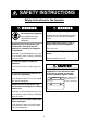
SAFETY INSTRUCTIONS Safety Instructions for the Operator WARNING WARNING Keep heater away from equipment. ELECTRICAL SHOCK HAZARD Do not open the equipment. A heater can melt the equipment's power cord, which can cause fire or electrical shock. Only qualified personnel should work inside the equipment. Keep combustible material (such as thinner) away from the equipment. Immediately turn off the power at the switchboard if water leaks into the equipment or something is dropped in the equipment.
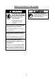
Safety Instructions for the Installer CAUTION WARNING ELECTRICAL SHOCK HAZARD Ground the equipment to prevent electrical shock and mutual interference. Do not open the equipment unless totally familiar with electrical circuits and service manual. Only qualified personnel should work inside the equipment. Turn off the power at the switchboard before beginning the installation. Fire or electrical shock can result if the power is left on.
TABLE OF CONTENTS FOREWORD......................................................................................................... iv SYSTEM CONFIGURATION ................................................................................. v EQUIPMENT LIST............................................................................................... vii 1. OPERATION .....................................................................................................1 1.1 Equipment Overview ...................
FOREWORD A Word to the Owner of the IB-782 FURUNO Electric Company thanks you for purchasing the IB-782 Multi-Communication Unit. We are confident you will discover why the FURUNO name has become synonymous with quality and reliability. For over 50 years FURUNO Electric Company has enjoyed an enviable reputation for quality and reliability throughout the world. This dedication to excellence is furthered by our extensive global network of agents and dealers.
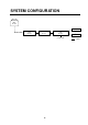
SYSTEM CONFIGURATION ANTENNA UNIT IB-180 IB-182 TEL or FAX COMMNUNICATION UNIT IB-282 JUNCTION BOX IB-313 MULTI-COMMUNICATION UNIT IB-782 TEL or FAX Max.
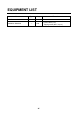
EQUIPMENT LIST Name Multi-Communication Unit Installation Materials Type Qty Remarks IB-782 — 1 set vi • Power cable (3 m) • Tapping screw (Φ4.5, 4 pcs.
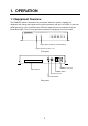
1. OPERATION 1.1 Equipment Overview The [POWER] switch is located on the rear panel. When the power is applied, the diagnostic test checks the equipment for proper operation, and the “Line LEDs” on the front panel light and go off in numerical order. After the diagnostic test is completed, only the power lamp lights. The 1A circuit protector protects the equipment from overcurrent.
1.2 Calling Below is the procedure for how call a land subscriber, make a ship-to-ship call. 1. Pick up the handset and dial “0” (number for connecting with Inmarsat services). Listen for the dial tone. 2. Enter subscriber’s complete number (vessel ID no.), then press the [#] button. Land subscriber 0 0 LES No. # Service Country Area Code Code Code Subscriber's No. End Code Ship-to-ship call 0 LES No. 0 Service Code # Sea Area No. Vessel ID No. (Inmarsat A or B) End Code Sea area no.
1.4 Intercom The intercom function is available when two or more telephones are connected to the IB-782. It allows communication between the telephones of the IB-782 and the telephones/handset of the communication unit IB-282 and between the telephones of the IB-782.
Calling from communication unit’s telephone to IB-782’s telephone 1. 2. 3. 4. Pick up the receiver and listen for the dial tone. Dial [*], [3], [0], party’s extension number (1-8), [#]. Talk with party. Hang up the receiver upon completion of the call. 1.5 Forwarding a Call A call may be forwarded to another telephone as follows: How to forward a call 1. Without hanging up the receiver, press the [HOOK] key. 2. Dial telephone extension number and [#]. 3.
1.7 Receive-Only Telephone Any telephone connected to the IB-782 can be designated as a “receive-only telephone.” This requires setting of a DIP switch. For this procedure see paragraph 2.3. Setting From the telephone to set as “receive only”, dial [*], [5], [9], [1], [#] Cancelling From the telephone not designated as receive-only telephone, dial [*], [5], [9], [1] and the telephone number you wish to cancel as a receive-only telephone.
2. SETTINGS 2.1 PBX Mode Settings Set the PBX mode from handset connected to the communication unit of the FELCOM 82 to enable use of the IB-782. 1. Turn on the communication unit. 2. From the handset of the communication unit, press [FUNC Quit], [5], [9], [8] to display the OID/OID menu. 59OID/DID PBX Mode: ON ON/OFF Enter:[Ent] Quit: {Quit] OID/DID menu 3. Press the [ ] or [ ] key to select “PBX Mode” to ON.
2.2 OID/DID Setting Set the ID number of each telephone connected to the IB-782, from the handset connected to the communication unit. The two-digit ID number should be the same as the telephone no. (01-08); for example, TEL No. 2 would be “02.” ID numbers should be set after setting the PBX mode, the instructions for which appear in the paragraph 2.1. 1. Turn on the communication unit. 2. From the handset, press [FUNC Quit], [5], [9], [3].
2.3 DIP Switch Setting SW No. 1 2 3 4 Function How to connect to Inmarsat services — Receive only — Default Setting OFF ON OFF OFF ON Connect with OFF HOOK. Fixed at “ON.” YES — OFF Connect by dialing 0 or 9. — NO Fixed at “OFF.” 2.4 Changing Number for Connection to Inmarsat Services The number for connection to Inmarsat services can be 9 or 0. Dial as below to select number desired.
3. MAINTENANCE WARNING Do not open the equipment. Only qualified personnel should work inside the equipment. 3.1 Cleaning Dust or dirt can be removed from the equipment with a soft, dry cloth. Do not use chemical cleaners to clean the equipment – they may remove paint and markings.
4. INSTALLATION 4.1 Mounting Mounting considerations The IB-782 can be mounted on a desk or on a bulkhead. Keep the following points in mind when selecting a mounting location: • Leave sufficient space around the unit for maintenance and servicing. • Locate the unit away from direct sunlight because heat can build up inside the cabinet. • Install the unit near the telephone or facsimile which is to be connected. • The mounting location should be stable and moderate in temperature and humidity.
4.2 Wiring Follow the illustration below to wire the IB-782. MULTI-COMMUNICATION UNIT IB-782 TEL8 - TEL1 LN8-LN1 LINE LN0 POWER 100V-220VAC 50-60Hz 1A Ground Terminal 100-220 VAC Power Cable (supplied) To Communication Unit IB-282 CAUTION Ground the equipment to prevent electrical shock and mutual interference. TEL3 5 6 Junction Box IB-313 Local Supply (Use TTYCS-1 (Japan Industrial Standard) or equivalent.) Armor Shield Conductor Rosette MJ-2S S =1.25 mm 2 =1.
SPECIFICATIONS OF THE MULTI-COMMUNICATION UNIT IB-782 1. GENERAL (1) Outside line 1 (2) Extension line 8 (3) Dialing Method NTT PB signal 2. POWER SUPPLY (1) Main Unit 100-220 VAC, 1 phase, 50-60 Hz, 20 VA (2) Power Consumption 10 W or less 3. ENVIRONMENTAL CONDITION (1) Ambient Temperature -15°C to +55°C (2) Relative Humidity 93% at 40°C (3) Water proofing Main Unit: IPX2 (4) Vibration IEC 60945 4. COATING COLOR (1) Main Unit Panel: N3.0 Newtone No. 5, Cover: 2.5GY5/1.