Installation Guide v1.0 MFD8/12/BB READ ME FIRST! Please read this document before installing and powering ON your NavNet Display INSTALLATION TOOLS YOU WILL NEED: An ordinary USB MOUSE AND USB KEYBOARD for the MFDBB Installation! These are also helpful with the MFD8/12 Installation. www.furunousa.
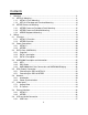
Contents 1. Mounting ................................................................................................................ 11 1.1. MFD8/12 Mounting ........................................................................................... 11 1.1.1. MFD8/12 Flush Mounting .......................................................................... 12 1.1.2. MFD 8/12 Desktop and Overhead Mounting ............................................. 14 1.2. MFDBB Processor Mounting ........................
2.9.2. Audio ......................................................................................................... 39 2.10. MFD8/12 Video, USB and Audio Connection ............................................... 39 2.10.1. Waterproof Connection .......................................................................... 39 2.10.2. Non Waterproof connection .................................................................... 42 3. Configuration ..............................................................
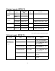
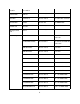
Standard supply (MFD8/12) Name Multi Function Display Installation materials Spare Parts Accessories Part Number (PN) Qty MFD8 - 1 MFD12 - Type CP19-00900 000-011-780 CP19-01000 000-011-781 SP19-00701 001-028-020 SP19-00801 001-028-030 FP19-01101 001-023-060 Remarks Choose one. 1 set For MFD8, CP19-00901*, cables For MFD12, CP19-01001*, cables 1 set For MFD8, fuses For MFD12, fuses 1 set Panel/Bezel Removal tool *See the lists at the end of this manual.
M12-05BFFM-060 000-167-967 φ6, 6 m, NMEA2000, w/micro connector MOD-Z072-020+ 000-167-175 LAN cross, 4-pair, 2 m MOD-Z072-050+ 000-167-176 LAN cross, 4-pair, 5 m MOD-Z072-100+ 000-167-177 LAN cross, 4-pair, 10 m MOD-Z073-030+ 000-167-171 LAN straight, 2-pair, 3 m MJ-A6SPF0016-005C 000-159-689 For FAX-30, ETR6N/10N connection LTWSS050505FMFTS001 000-168-603 NMEA 2000 “T” Connector, micro LTWMC-05BMMTSL8001 000-168-604 NMEA 2000 terminator, male, micro LTWMC-05BFFTSL8001 000-168-605
RJ45 Junction Box RJ45-to-RJ45 Straight RJ4-5CN-STR For Mast-Step or LAN cable extension Connector Boot 001-028-090 Waterproofing Kit for MFD8/12 exposed connection points OP19-7 Operator’s Manual OME-4440 NMEA 2000 Interface Unit 000-167-802 IF-NMEA2K1 - 7 Use where NMEA2000-toAD10/0183 Data conversion is required for legacy products
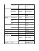
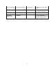
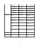
Standard supply (MFDBB) Name Type Code No. Qty Processor Unit MPU-001 - 1 Control Unit MCU-001 - 1 Display Control Unit DCU12 - 1 Remarks Choose one.
Rectifier RU-1746B-2 - Network Hub HUB-101 - Joint Box TL-CAT-012 000-167-140-10 For LAN cable extension Junction Box FI-5002 000-010-765 For NMEA 2000 Control Unit MCU-001 - Display Control Unit DCU12 - Cable Assy MJ-A7SPF0007-050C 000-154-028-10 5 m, NMEA0183, w/7P connector MJ-A6SPF0016-005C 000-159-689-11 For FAX-30, ETR6N/10N connection MOD-Z072-020+ 000-167-175-10 2 m, LAN MOD-Z072-050+ 000-167-176-10 5 m, LAN MOD-Z072-100+ 000-167-177-10 10 m, LAN MOD-Z073-030+ 00
NMEA connector CB-05PM+05BF-020 000-167-969-10 φ10, 2 m, NMEA 2000 CB-05PM+05BF-060 000-167-970-10 φ10, 6 m, NMEA 2000 CB-05BFFM-010 000-167-971-10 φ10, 1 m, NMEA 2000 CB-05BFFM-020 000-167-972-10 φ10, 2 m, NMEA 2000 CB-05BFFM-060 000-167-973-10 φ10, 6 m, NMEA 2000 LTWSS-050505-FMFTS001 000-168-603-10 NMEA 2000 distributor (micro style) LTWMC-05BMMTSL8001 000-168-604-10 NMEA 2000 terminator, male (micro style) LTWMC-05BFFTSL8001 000-168-605-10 NMEA 2000 terminator, female (micro styl
1. Mounting 1.1. MFD8/12 Mounting MFD8 MFD12 When selecting a mounting location for the NN3D MFD8/12, keep the following in mind: • The temperature and humidity of the mounting location should be moderate and stable. • Install the unit away from exhaust pipes and ventilators. • The mounting location should be well ventilated. • Mount the unit where shock and vibration are minimal. • Keep the unit away from electromagnetic field generating equipment such as motors and generators.
1.1.1. MFD8/12 Flush Mounting 1. Prepare a cutout in the mounting location using the template sheet (supplied) for the MFD8 or 12. 2. Remove the front panel from the MFD by grasping it at its sides and pulling it towards you. 3. Attach the mounting gasket (sponge) to the display unit. 4. Fix the display unit by using four self-tapping screws (supplied). 5.
How to detach the front cover when flush mounted. To detach the front panel when the unit is flush mounted, use the special tool (supplied) as below. Note that the front cover may be damaged if this procedure is not followed! 1. Insert the tool in the notch on the lower side of the unit 2. Pull the tool to raise the panel slightly. Repeat this action for all notches on the lower side of the unit 3.
4. Use your hands to detach the front panel from the lower side. 1.1.2. MFD 8/12 Desktop and Overhead Mounting Follow the procedure below to mount the MFD8 or 12 on a desktop or overhead. 1. For MFD12, attach the liner to each side of the display unit. (Reverse the MFD12 Liners for overhead mounting.) 2. Fix the bracket (Hanger) by using self-tapping screws (supplied). 3.
1.2. MFDBB Processor Mounting The unit can be mounted on the deck, a desktop or on a bulkhead. Take special note that the MFDBB IS NOT WATERPROOF. Select a mounting location considering the points below: • Select a location where temperature and humidity are moderate and stable. • Consider the lengths of the cables connected among the processor unit, radar sensor and control unit.
1.2.2. MFDBB Processor Bulkhead Mounting Mark four fixing holes positions on the bulkhead. Screw in two 6x30 self-tapping screws at upper fixing positions, leaving 5 mm protruding. Set the processor unit to the screws and screw in two self-tapping screws at lower positions. Tighten all screws. 1.2.3. MDBBB Keyboard Mounting The BlackBox keyboard (control unit MCU-001) is designed to be flush mounted in a console or panel. 1.
How to detach the front panel when flush mounted To detach the front panel when the unit is flush mounted, use the tool (supplied) as below. Do not attempt to remove it by any other method, to prevent damage to the unit. 1.
2. Pull the tool to raise the panel slightly 3. Similarly use the tool to raise the panel at the right-side notch. 4. Insert the tool to the space at the one end of the unit, and pull it to raise the panel slightly. Repeat this procedure for the opposite side 5. Use the tool to raise the panel at the two notches on the upper side of the unit. 6.
2. Wiring 2.1. Overview 2.1.1.
2.1.2. MFDBB Overview 2.2. Power Connections 2.2.1. MFD8/12 The MFD8/12 can be powered directly using nominal 12V or 24V DC. Only use the power cable supplied with the unit and connect it to the Power Connector at the rear of the unit. 2.2.2. MFDBB The MCU001 - MFDBB processor unit can be powered using 12V or 24V. Make the power cable as shown below.
To connect the power cable, remove the Power Terminal cover. Unfasten the four pan head screws and connect the power cable to the power terminal (upper: +, lower: -). Reattach the cover. Note that the recommended maximum cable length is 5 m.
2.3. DATA Ports (NMEA0183) 2.3.1. Overview Every MFD8/12 and MFD BB has THREE full NMEA0183 I/O Data Ports. One is available on the DATA1 7-Pin Connector and is pin compatible with Navnet 1/vx2 DATA1 Connector. Two additional NMEA Ports are available on the DATA2 18-Pin connector. These NMEA connections can accept a baud rate of 4800 or 38.4K. Any instrument (GPS, AIS, Smart Sensor, etc…) can be connected to any port.
Wiring Information Pin No. Color Function 7 Shield Shield 6 Black GND 5 Red 12V_OUT 4 Green RD1-C 3 Yellow RD1-H 2 Blue TD1-B 1 White TD1-A 2.3.3. DATA 2 Description DATA2 can be used to connect additional NMEA 0183 instruments. Use the included cable assembly FRUDD-18AFFM-L180 (FUSA P/N 000-164-608). This included PigTail Cable has an 18-Pin connector. DATA2 also provides additional Inputs/Outputs (Buzzer, Event …).
Wiring Information Pin No. Color Function Remark (Port No.) 18 Light green NET-C IN (0V) NMEA 2000 Power IN. When 12V DC power is applied on these pins, the N2K port will be powered (up to 1 ampere) 17 Pink NET-S IN (+12V IN) 16 Purple Shield 15 White BUZZER or EVENT IN External Buzzer Output or MOB/Event Input (Contact Closure) 14 Gray SPEED-ALARM C 13 Yellow SPEED-ALARM H Speed alarm contact.
2.4. NMEA2000 Description and Information 2.4.1. MFD Every MFD has one NMEA2000 port (Standard “DeviceNet Micro” style connector). This port is not powered unless External Power is applied on Pin 18 and 17 of DATA2 and must be connected to a properly configured NMEA2000 network. IMPORTANT: Each MFD is designed to connect to separate NMEA2000 Networks/Backbones! All MFD and DRS use “Ethernet Bridging” to link separate NMEA2000 networks/backbones.
2.4.3. NMEA2000-0183 Data Conversion and NMEA2000 Bridging NMEA0183 to NMEA2000 conversion NMEA0183 sentences and NMEA2000 PGNs, which are used and accepted in the MFD network can be converted and output in either/both NMEA0183/NMEA2000 formats. Note that only one type of data can be converted and output at a time (one position, one depth, one heading…). In case of multiple GPS, the position output is the one currently selected in an MFD network.
2.5. DRS (Radar) Connection Up to two DRS (Digital Radar Sensors) can be connected to a NavNet3D network. Every DRS comes with a supplied 15 Meter cable (FUSA P/N 000-167-636). Other cable lengths may be purchased if necessary (Note that the part numbers for the DRS25A are different): - 10 Meter Cable (FUSA P/N 000-167-635) - 20 Meter Cable (FUSA P/N 000-167-637) - 30 Meter Cable (FUSA P/N 000-167-638) The Radar cable is a “Siamese” type cable that carries power (48V) and Data (Ethernet).
2.5.1. Connecting the DRS to MFD8/12 Standalone Installation: When the MFD8/12 and the Radar are the only Ethernet sensors, you can connect the Radar Ethernet connection directly to the back of the MFD8/12. Network Installation: As soon as multiple MFD8/12 or other Ethernet sensors (i.e. DFF1 Fish Finder, BBWX1 Sirius receiver, etc.) are used, the Radar Ethernet connection must be connected to an Ethernet Hub.
Example of straight Ethernet Coupler (FUSA P/N= RJ4-5CN-STR): Note: This Ethernet coupler is not waterproof. Ethernet Cables that can be used to extend the Ethernet Radar Connection: - 2 Meter RJ45 to RJ45 Ethernet Cable (P/N 000-167-175) - 5 Meter RJ45 to RJ45 Ethernet Cable (P/N 000-167-176) - 10 Meter RJ45 to RJ45 Ethernet Cable (P/N 000-167-177) Please refer to the DRS Installation Guide for more information on connections inside the antenna 2.5.1.
2.6. Network 2.6.1. Introduction NavNet3D (just like NavNet1 and VX2) uses standard TCP/IP Ethernet to share radar/sounder images and other navigation information from devices connected within a networked system. In any single NavNet 3D network, a combination of up to ten NavNet3D MFDs may be connected to each other. All NavNet3D Network Components have one integrated regular RJ45 Ethernet port (with the exception of the MFDBB which has an integrated hub).
two ports are NOT standard POE (Power over Ethernet) and POE devices cannot be connected to these two ports. 2.6.2. Power Synchronization A NN3D network is a system in which all components share information (navigation data, settings, points, routes, etc) with each other. Furuno developed special Power Synchronization features to allow proper network synchronization and functionality. Sleep Mode: The MFDs have a special “sleep mode” that allows each MFD to process data while consuming low power.
Why use the Furuno HUB (HUB101): The Furuno HUB101 allows the Power Synchronization signal to reach the MFDs and other Power Synchronization compatible devices.
The MFDBB processor unit has an Internal Hub that is compatible with Power Synchronization. DIP switches inside the processor unit can be turned ON or OFF to enable/disable the Power Synchronization feature. The number on each DIP switch corresponds to the port number. Additionally, to allow the Power Synchronization to work, a setting in the NN3D MFD’s Software “Installation Wizard” must be turned ON (see Chapter 3 for more information) 2.7.
be viewed only on the MFD where the source is connected. Additionally some IP Camera can be controlled from NavNet3D (Pan-Tilt–Zoom ((PTZ)) IP Cameras only) 2.7.1. Analog Video MFD8/12 The MFD8/12 units have 2 Analog Video inputs (PAL/NTSC) on 2 mm RCA (cinch) type connectors located on the rear of the display MFDBB The MFDBB unit has 4 Analog Video inputs (PAL/NTSC) on BNC type connectors (75 Ohms) located on the processor unit 2.7.2.
The IP cameras need to have a specific assigned IP address (from 172.31.200.003 through 006).
2.8. External Monitors 2.8.1. MFD8/12 A DVI monitor can be connected to the MFD8/12 to repeat the screen at a remote location. The plug is DVI-D format and only a DVI monitor can be connected. The MFD8 has a 640x480 (VGA) DVI-D output. The MFD12 has an 800x600 (SVGA) DVI-D output. Furuno offers the following DVI cable: - 5 Meter DVI Cable (FUSA P/N= 000-149-054) - 10 Meter DVI Cable (FUSA P/N= CBL-DVI-10M) Please refer to 2.10.1Waterproof Connection when Waterproof is needed 2.8.2.
When Extended Mode is used the two screens need to be located in close proximity to each other. The two monitors show independent screen displays that can be configured independently. Only one Keyboard is used to control both monitors (the cursor will “jump” back and forth from monitor to monitor).
mouse software is permitted. However, the standard Mouse HID drivers will load automatically, allowing most mice and wireless mice to work fine. Generic USB keyboards may be used to enter Name and Numerical Position.
2.9.2. Audio Audio In and Audio out are reserved for future Development Note: If Sirius Satellite Radio control and functionality is desired in the future, be sure to use the Audio Outputs on the Sirius Receiver (BBWX1) itself and not from an MFD! 2.10. MFD8/12 Video, USB and Audio Connection The DVI, USB, Analog Video Input and Audio In/Out ports are behind the connector cover on the rear panel. To access to the ports and connect the cables, please refer to the instructions below.
2. Pass DVI-D, VIDEO, AUDIO and/or USB cables through the fixing plate (supplied). 3. Attach each connector to the appropriate location at the rear of the display unit. 4. Pass cables through the slit on the boot cover. 5. Install the rubber stopper to each cable. The largest hole is for the DVI-D cable.
6. Use the four plate screws (M3x10, supplied) to fasten the fixing plate and boot cover to the display unit. 7. Slide the rubber stopper into the hole of the rubber boot, and fasten the cable tie to hold the rubber boot and stopper. Note: When only the Ethernet, Power, DRS, DATA1, DATA2 and NMEA2000 connection are used the Waterproof Connector boot is not necessary.
2.10.2. Non Waterproof connection When you do not need waterproofing, use the cable fixing plate (supplied in standard installation materials). 1. Unfasten the four screws to detach the connector cover at the rear of the display unit. 2. Attach the cable fixing plate by using the binding screw (M3x10, supplied as the installation materials). 3. Attach each connector to the appropriate location at the rear of the display unit. 4.
3. Configuration 3.1. Introduction NavNet3D (just like NavNetVX2) uses Ethernet to share radar/sounder images and other navigation information from devices connected within a networked system. In any single NN3D network, a combination of up to ten NavNet3D MFDs may be connected to each other via Ethernet. All NavNet3D Network Components have an integrated regular RJ45 Ethernet port for this purpose.
3.1.1. Selecting a Master When multiple MFDs are connected in a network, one MFD (and only one) needs to be designated as the “Master”. The MFD set as Master will act as a “DHCP server” and automatically performs the network configuration of all the other MFDs in the network. (The Master sets up the Hostnames, IP addresses etc…). Note: The notion of “Master” and “Slave” is only an installation setting and is totally transparent to the end user.
“Own Setting” Tab This Tab configures the local ports of the MFD (NMEA0183 Input/Output, NMEA2000 Output) on which the Installation Wizard is currently used. This is also where the Master can be designated (DHCP Server turned ON) “Global” Tab This Tab contains configuration information that is global to the system and shared among MFDs. This is the section where the Data Source (Sensors) can be selected to be used as primary information. You will be able to customize sensor names (ex.
-The system will search for sensors on the network. Allow the system to fully perform the search (which takes about 30 seconds). Do not click the Skip button. -After the detection, the language selection screen appears. The default language is English. Use the Cursor Pad and the center click (or the mouse for the MFDBB) then click on “Next: 3.2.1. Own Settings (Master, Power Synchronization, Monitor) To set up an MFD as a Master, just set the “DHCP server setting” as “Enable”.
Note: Power Synchronization requires a HUB101 and proper hardware configuration. Please refer to 2.6.2 Power Synchronization paragraph for more Information Note: On the MFDBB, the same page allows you to select the monitor resolution and the Dual Screen mode configuration (when two monitors are used). Leave the DVI Resolution to “AUTO” (this default setting will work for most installation configurations). Please refer to 2.8.
External Monitor for more information on Clone and Extended mode when two monitors are connected to a single MFDBB processor. After enabling the DHCP server click on “Exit” to validate the setting. The MFD will Power OFF automatically! Power ON the “Master” MFD. Wait a few minutes until the Installation Wizard appears on the Master then power ON all the other MFDs in the network and continue the Installation Wizard configuration on the Master MFD.
Click on the “Next” button to continue the configuration. 3.2.3. NMEA0183 The three “NMEA0183 Port” tabs are used to configure the Input and Output of the individual MFD’s own NMEA0183 ports. It is important to understand that it is not possible to filter any received NMEA0183 Data at any of these ports on individual MFDs.
IMPORTANT!: After configuring any NMEA0183 Input Port Sensors on the Master MFD, you must REPEAT THIS PROCEDURE at any other Slave MFDs in the network where you have connected NMEA0183 Input Sensors!! If this is not done, the sensors will not be available for selection as a Primary System Data Source in the Global Settings Tab.
the raw GPS fixes. A setting between 000 to 999 is available. The higher setting the more smoothed the raw data, however too high a setting slows response time to change in latitude and longitude. This is especially noticeable at high ship’s speeds. Increase the setting if the GPS fix changes. SOG/COG Smoothing During position fixing, ship’s velocity (speed and course) is directly measured by receiving GPS satellite signals.
is available again or the alarm is acknowledged (by key operation). Off: Alarm sounds three times. -After completing the NMEA0183 Configuration Procedures on the Master and Slave MFDs, return to the Master MFD to complete the installation process. -Click “Next” at the Master MFD to continue the configuration 3.3. Installation Wizard Global Settings Usually, the Global Settings are performed from the Master MFD in the network 3.3.1.
Note: The currently accepted engine data is as follows: - Engine Parameters (PGN 127488) Engine Speed Engine Boost Pressure - Engine Parameters (PGN 127489) Engine Oil Pressure Engine Temp Engine Temperature Status Engine Warning Status Click on “Next” to continue the configuration 3.3.2. Assigning Nicknames You can assign Nicknames to every Ethernet Sensor, NMEA2000 instrument/sensor/display and NMEA0183 Receive Port for every MFD in a network.
Note: This page will display the NMEA0183 Input Ports of every MFD connected to the network as “Port1”, “Port2” and “Port3”. Each port refers to the MFD listed just above.
3.3.3. Camera Names You can assign names to each connected Analog and IP Camera. These names will be used by the RotoKey and for the Video ID in the main interface. The IP Camera names are Global and only need to be configured at the Master MFD. However, the Analog cameras must be named at each MFD where they are connected. Please refer to the Appendix “How to configure the AXIS IP Camera” for more information. Note: “PnP” refers to the Analog Connection (Picture in Picture).
“Own” settings for each MFD(s) before being able to select the corresponding instruments as a data source. Select the “Data Source” Tab. This tab allows you to select the Primary System Data Source for various data types used by the Navnet 3D Network. Name Description Example Position & SOG/COG Choose the position-fixing sensor to use.
Water Depth Choose the depth sensor to use. Smart sensor (NMEA 0183), Speed sensor (ETR), Smart sensor (NMEA 2000), Other (NMEA 0183) Water Temperature Choose the temperature sensor to use. Smart sensor (NMEA 0183), Speed sensor (ETR), Smart sensor (NMEA 2000), Other (NMEA0183) Wind Choose the wind sensor to use. FI-501/502, PB-100, WS200, PB-200, Other Date & Time Choose the date and time source to use.
3.3.5. Sounder Configuration Up to 2 Network sounders can be connected on the NavNet3D network. DFF1 and DFF3 Select the Sounder Source: a) Click the Transducer Setup pull-down menu, and choose Model Number, TD-ID or Manual, according to the transducer connected. Model Number: Furuno’s transducer TD-ID: Airmar’s transducer w/TD-ID Manual: Other Transducers b) If Model Number is selected, click the High Frequency and Low Frequency pulldown menus, and choose the applicable model type.
Up-down: Set the distance from the transducer to the antenna unit in the vertical direction. Port-starboard: Set the distance from antenna unit to the transducer in port-starboard direction. When the transducer is located on the starboard side, set a positive value. e) Click the Motion Sensor pull-down menu, and choose SC-30 or SC-50/110 if connected. f) Set the transducer position at the Transducer Position pull-down menus.
3.3.6. DRS (Radar) Configuration Up to two DRS can be connected on the NavNet3D network. - Select the Radar Source you want to configure - Click the Antenna Height pull-down menu, and choose the height of the antenna above the waterline, among under 10ft, 10ft-30ft or over 30ft. - Perform the heading adjustment as follows. - Steer towards a suitable visible target(for example, moored ship or buoy). - Click the Range pull-down menu, and choose a range between 0.125 and 0.25 nautical miles.
- Click the Push STBY button to stop the transmission. Click on “Exit”. This will close the Installation Wizard and launch NN3D When the Agreement appears on the display, push RotoKey to agree. Important: If you are using a MFDBB, the Keyboard will not work until it is properly “Linked” to a processor unit. Please refer to 3.
MFDBB Keyboard/Processor Linking then continue to the next paragraph to finish the Radar Installation. When the MFD displays the main interface, push the [MENU] key. Use the RotoKey to scroll to the “Radar” page. Use the Cursor Pad or the mouse and click on “Radar Source” to select the DRS you want to use. Press the [MENU] key to close the Menu then press the [DISP] key. Use the RotoKey to select a Radar screen and push to validate the selection.
3.4. MFDBB Keyboard/Processor Linking MFDBB Keyboards are Ethernet network devices that need to be assigned (linked) to a specific MFDBB processor unit during installation. A special “key-push” sequence is used to cycle through the “Linking Codes” for all the MFDBB processor unit(s). If only one MFDBB processor unit is on the Network: Simultaneously press and hold the Left key of the Scrolling Pad, the Right key of the Cursor pad and push the RotoKey for 5sec.
4. Registering the System 4.1. SystemID Description The Navnet 3D SystemID is a unique number assigned to a complete NN3D networked system with one or more MFDs. On the same boat, all networked MFDs have the same SystemID. This number will not change if a MFD or other NavNet Component is added to the system. The SystemID is used to identify the customer when he purchases data or services.
5. Appendix 5.1. Example NN3D System Configurations 5.1.1. Basic Plotter/Fish Finder Installation The Furuno GPS (FUSA P/N BBWGPS) is directly connected to 7-Pin Port DATA1 of the MFD. The DFF1 Fish Finder (FUSA P/N DFF1) is directly connected to the Ethernet port of the MFD using the standard supply cable (3Meter).
5.1.2. Basic Plotter/Radar/Fish Finder Installation This is a single station Plotter/Radar/Fish Finder installation. The Furuno GPS (FUSA P/N BBWGPS) is directly connected to 7-Pin Port DATA1 of the MFD. Since two Ethernet sensor are on the network (DRS Radar and Fish Finder), a network switch (FUSA P/N HUB101) is necessary. In this case the Radar Power Cable is directly connected to the back of the MFD8/12 (DRSxD (Domes) can be powered directly by any MFD. For DRSxA (Open) check compatibility).
Additional Furuno Network Sensors can also be plugged directly to the HUB (using a regular Ethernet cable): - FA30 AIS Receiver/FA50 AIS Class B Transponder - BBWX1 Sirius Satellite Weather Receiver - FAX30 - Weather Fax Receiver 67
5.1.3. Dual MFD Installation Example This installation is a dual MFD installation with Radar Overlay and ARPA functionality (PG500 Heading Sensor included). The Furuno GPS (FUSA P/N BBWGPS) is directly connected to 7-Pin Port DATA1 of the MFD. The Furuno Heading Compass (FUSA P/N PG500) is connected to port DATA2 of the MFD. Note that in this installation, the DRS is a 12kW “DRS12A” and therefore an optional power supply (PSU12) is required to supply power to the DRS12.
5.1.4. Dual Screen MFDBB Installation with Pilot Integration Navpilot 500 Series Integration with NN3D MFDs is similar to Navnet vx2 integration. One difference is that NN3D MFDs no longer have an AD10 Heading Port. However, NN3D MFDs do require high speed NMEA0183 heading information (10Hz) for ARPA functionality.
In this example, the MFDBB is configured for Extended Mode. The two monitors show independent screen displays that can be configured independently. Only one Keyboard is used to control both monitors (the cursor will “jump” back and forth from monitor to monitor). The two screens need to be located in close proximity to each other.
5.2. Configuring AXIS IP Cameras 5.2.1. Introduction: In order to view and control Axis IP Cameras from an MFD in a Navnet 3D network, it is first necessary to assign the IP Address of a MPEG-4 capable AXIS IP Camera. This procedure will require a Windows PC connected via Ethernet to the AXIS IP Camera(s). Pre-wiring and installing the cameras on the vessel first is recommended so that all AXIS IP cameras can be networked to the PC through a Hub and can be configured at the same time.
Right Click on “Local Area Connection” and select “Properties” Select “Internet Protocol (TCP/IP)” and click on “Properties” Fill the IP fields as shown below. Click on OK to confirm and close the 2 windows.
Note that the new IP can take up to 20 seconds to be recognized. A pop-up in the lower right corner should show when the IP is correctly set. Turn OFF any Firewall that could prevent data to be exchanged between NavNet and the PC. You may also have to restart your computer. 5.2.3. Set up the IP address of the camera To work with NavNet3D, the IP cameras need to be set up with specific IP Addresses. Up to 4 IP cameras can be connected on a network. IP Camera number 1 = 172.031.200.
Click on “Copy to PC” The following window should appear.
The AXIS IP utility will detect all the IP cameras connected on the network Note: If you use the same camera models in multiple locations, BE SURE to WRITE DOWN the IP Camera serial number (that can be found on the back of the camera) with the intended location to help correctly assign the IP camera’s name.
You will need to restart (power OFF and ON) the camera after the address is changed. (Just unplug and plug back the Ethernet cable if you are using the POE). It can take a while before the confirmation box appears. Click the “Close” button.
5.2.4. Configure the camera The cameras need to be configured using a Internet Explorer. Enter the IP address of the first IP camera: Set the password of the IP camera to “pass” and click “OK” Important: You cannot use another password and must use the word “pass”. When you press OK, a dialog box asking for a login/password will appear. Just use “root” and “pass”.
When the webpage loads, pay attention to the top of the page to authorize the installation of the ActiveX.
1) In “Basic Configuration -> Users” select “Enable anonymous viewer…” and click on “Save” 2) In “Basic Configuration -> Date and Time” select “Synchronize with computer time” and click on “Save” 3) In “Live View Config -> Layout” select “MPEG4” as the default video format and click on save 4) Optional: When using a PTZ (moving) camera, you can set-up the default “Home” position.
When the view is correctly set up, type “Home” for the Current position and select “Use current position as Home”. Click on “Add” to validate. If you don’t want the camera to return to the “Home” position automatically after 30 sec, just put 0 and validate.
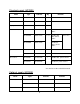
UNIT MFD8-J/E 001-028-050-00 CP19-00901 000-157-995-10 MJ-A3SPF0017-050ZC 000-164-608-10 FRUDD-18AFFM-L180 000-164-609-10 ** 1 1 1 Q'TY 1 1 1 1 CP19-00900 MOD-WPAS0001-030+ 001-023-060-00 FP19-01101 001-028-020-00 SP19-00701 000-011-776-00 MFD8-J/E DESCRIPTION/CODE № LIST (略図の寸法は、参考値です。 DIMENSIONS IN DRAWING FOR REFERENCE ONLY.) 2.(*1)は、それぞれ仕様選択品を表します。 (*1)INDICATE SPECIFICATION SELECTIVE ITEM. 1.
UNIT MFD12-J/E 001-028-060-00 CP19-01001 000-153-769-11 MJ-A3SPF0027-050ZC 000-164-608-10 FRUDD-18AFFM-L180 000-164-609-10 ** 1 1 1 Q'TY 1 1 1 1 CP19-01000 MOD-WPAS0001-030+ 001-023-060-00 FP19-01101 001-028-030-00 SP19-00801 000-011-778-00 MFD12-J/E DESCRIPTION/CODE № LIST (略図の寸法は、参考値です。 DIMENSIONS IN DRAWING FOR REFERENCE ONLY.) 2.(*1)は、仕様選択品を表します。 (*1)INDICATE SPECIFICATION SELECTIVE ITEM. 1.
ᢙ㊂ 3 6; ↪ㅜ㧛⠨ 4'/#4-5 ⇟ ภ 01 $+0&+0) *'#& 5%4'9 㩔㩨㨼㩧㩎㩨ዊ㩒㩆㩨 %#$.'ޓ6+' 㩄㩧㩗㩨㨹㩂㩇 5'.( 6#22+0) 5%4'9 㩎㩡㩇㩊㨹㩕㩩㩧㩒㩆㩨 ޓ㩆㨷 %#$.' (+:+0) 2.#6' 㩃㨺㩖㩨㩣ᜬ㊄ౕ (75' .#$'. 㩕㨷㨺㩇㩨㩔㩢㩙㨺㩂 /1706+0) 5210)' (㩙㨽㩧㩎㩠㨽㩇㩘㩩㩧㩆㩨 ฬޓޓ⒓ 0#/' /(& ⇛ޓޓ࿑ 176.
2#0'. 4'/18'4 㩔㩩㩒㩣㩢㩛㨺㩔㩨㨺 .%& %.'#0+0) %.16* 㩖㨲㩣㩊㨺㩂㩢㨺㩏㨺 ฬޓޓ⒓ 0#/' ⇛ޓޓ࿑ 176.+0' %1&' 01 %1&' 01 ဳฬ㧛ⷙᩰ &'5%4+26+105 (2 6;2' ᢙ㊂ 3 6; ↪ㅜ㧛⠨ 4'/#4-5 #; : 㧲㨁㧾㨁㧺㧻ޓ㧱㧸㧱㧯㨀㧾㧵㧯ޓ㧯㧻ޓ㧚㧘㧸㨀㧰 㧔⇛࿑ߩኸᴺߪޔෳ⠨୯ߢߔ&ޓޕ+/'05+105 +0 &4#9+0) (14 4'('4'0%' 10.; 㧕 #; : ဳᑼ 㩄㨺㩎㩨⇟ภ߇㧞Ბߩ႐วޔਅᲑࠃࠅᲑߦઍࠊࠆㆊᷰᦼຠߢࠅޔ߅ߥޓޕߔ߹ߡߞ߇߆ࠄߜߤޔຠ⾰ߪᄌࠊࠅ߹ߖ ࠎޕ 691 6;2'5 #0& %1&'5 /#; $' .+56'& (14 #0 +6'/ 6*' .
/(& (75' ).#55 67$' 6;2' 㩕㨷㨺㩇㩨 (75' ).#55 67$' 6;2' 㩕㨷㨺㩇㩨 ()$1 8 # ()$1 8 # 2$( 2'4 8'5 $# : ဳᑼ 㩄㨺㩎㩨⇟ภ߇㧞Ბߩ႐วޔਅᲑࠃࠅᲑߦઍࠊࠆㆊᷰᦼຠߢࠅޔ߅ߥޓޕߔ߹ߡߞ߇߆ࠄߜߤޔຠ ⾰ߪᄌࠊࠅ߹ߖࠎޕ 691 6;2'5 #0& %1&'5 /#; $' .+56'& (14 #0 +6'/ 6*' .19'4 241&7%6 /#; $' 5*+22'& +0 2.#%' 1( 6*' 722'4 241&7%6 37#.+6; +5 6*' 5#/' 5'65 2'4 8'55'. $1: 01 2 4'/#4-5 %1&' 01 $# : 52#4' 㧔⇛࿑ߩኸᴺߪޔෳ⠨୯ߢߔ&ޓޕ+/'05+105 +0 &4#9+0)(ޓ14 4'('4'0%' 10.
Oct.22'07 R.
Oct.22'07 R.
Oct.23'07 R.
Oct.23'07 R.
1 2 MODEL FUSE(12/24V) MFD8 10/5 A MFD12 20/10 A MJ-A3SPF0017(MFD8) A マルチファンクションディスプレイ MULTI FUNCTION DISPLAY DVI_D MFD8/12 POWER IN J7 *3 1 NC NC TMDS_DATA1_N TMDS_DATA1_P TMDS_DATA1_3_SHIELD NC NC 5V_OUT+ GND HOT_PLUG_DETECT TMDS_DATA0_N TMDS_DATA0_P TMDS_DATA0_5_SHIELD NC NC TDMS_CLOCK_SHIELD TDMS_CLOCK_P TDMS_CLOCK_N 7 8 9 10 11 12 13 14 15 16 17 18 19 20 21 22 23 24 DVI-D/D S-LINK 5/10m,φ7 WHT 1 DC_INPUT+ TMDS_DATA2_P 2 12/24VDC MJ-A3SPF0027-050ZC(MFD12) 5m BLK 2 DC_INPUT- TMDS_DATA2_4_SHIELD
0 # / ' &1%7/'06 % 㩦 㨾㨼 %2 /, # 52( % # /1& 92#5 &8+ & & 5+0).'.
%#$.'ޓ6+' 㩄㩧㩗㩨㨹㩂㩇 5'.( 6#22+0) 5%4'9 㩎㩡㩇㩊㨹㩕㩩㩧㩒㩆㩨 ޓ㩆㨷 ฬޓޓ⒓ 0#/' ⇛ޓޓ࿑ 176.+0' %1&' 01 %8 0 %1&' 01 : 575 ဳฬ㧛ⷙᩰ &'5%4+26+105 %2 6;2' ᢙ㊂ 3 6; ↪ㅜ㧛⠨ 4'/#4-5 #; : 㧲㨁㧾㨁㧺㧻ޓ㧱㧸㧱㧯㨀㧾㧵㧯ޓ㧯㧻ޓ㧚㧘㧸㨀㧰 㧔⇛࿑ߩኸᴺߪޔෳ⠨୯ߢߔ&ޓޕ+/'05+105 +0 &4#9+0) (14 4'('4'0%' 10.; 㧕 #; : ဳᑼ 㩄㨺㩎㩨⇟ภ߇㧞Ბߩ႐วޔਅᲑࠃࠅᲑߦઍࠊࠆㆊᷰᦼຠߢࠅޔ߅ߥޓޕߔ߹ߡߞ߇߆ࠄߜߤޔຠ⾰ߪᄌࠊࠅ߹ߖ ࠎޕ 691 6;2'5 #0& %1&'5 /#; $' .+56'& (14 #0 +6'/ 6*' .
$+0&+0) *'#& 5%4'9 㩔㩨㨼㩧㩎㩨ዊ㩒㩆㩨 %108': 㩄㩧㩗㩨㨹㩂㩇 5'.( 6#22+0) 5%4'9 㩎㩡㩇㩊㨹㩕㩩㩧㩒㩆㩨 ޓ㩆㨷 %18'4 (+:+0) 2.#6' &8+㩀㩔㩨㨺㨿㩅㨾᧼ &8+ %18'4 &8+㩀㩔㩨㨺 /1706+0) 5210)' (㩙㨽㩧㩎㩠㨽㩇㩘㩩㩧㩆㩨 ฬޓޓ⒓ 0#/' ⇛ޓޓ࿑ 176.
/27 (75' 㩕㨷㨺㩇㩨 (75' 㩕㨷㨺㩇㩨 ()$1 8 # ()$1 8 # 2$( 2'4 8'5 #; : ဳᑼ 㩄㨺㩎㩨⇟ภ߇㧞Ბߩ႐วޔਅᲑࠃࠅᲑߦઍࠊࠆㆊᷰᦼຠߢࠅޔ߅ߥޓޕߔ߹ߡߞ߇߆ࠄߜߤޔຠ ⾰ߪᄌࠊࠅ߹ߖࠎޕ 691 6;2'5 #0& %1&'5 /#; $' .+56'& (14 #0 +6'/ 6*' .19'4 241&7%6 /#; $' 5*+22'& +0 2.#%' 1( 6*' 722'4 241&7%6 37#.+6; +5 6*' 5#/' 5'65 2'4 8'55'. $1: 01 2 4'/#4-5 %1&' 01 #; : 52#4' 㧔⇛࿑ߩኸᴺߪޔෳ⠨୯ߢߔ&ޓޕ+/'05+105 +0 &4#9+0)(ޓ14 4'('4'0%' 10.
2#0'. 4'/18'4 㩔㩩㩒㩣㩢㩛㨺㩔㩨㨺 ฬޓޓ⒓ 0#/' ⇛ޓޓ࿑ 176.+0' %1&' 01 ဳฬ㧛ⷙᩰ &'5%4+26+105 (2 6;2' ᢙ㊂ 3 6; ↪ㅜ㧛⠨ 4'/#4-5 #; : 㧲㨁㧾㨁㧺㧻ޓ㧱㧸㧱㧯㨀㧾㧵㧯ޓ㧯㧻ޓ㧚㧘㧸㨀㧰 㧔⇛࿑ߩኸᴺߪޔෳ⠨୯ߢߔ&ޓޕ+/'05+105 +0 &4#9+0) (14 4'('4'0%' 10.; 㧕 #; : ဳᑼ 㩄㨺㩎㩨⇟ภ߇㧞Ბߩ႐วޔਅᲑࠃࠅᲑߦઍࠊࠆㆊᷰᦼຠߢࠅޔ߅ߥޓޕߔ߹ߡߞ߇߆ࠄߜߤޔຠ⾰ߪᄌࠊࠅ߹ߖ ࠎޕ 691 6;2'5 #0& %1&'5 /#; $' .+56'& (14 #0 +6'/ 6*' .19'4 241&7%6 /#; $' 5*+22'& +0 2.#%' 1( 6*' 722'4 241&7%6 37#.
Jun.27'07 R.
Jun.27'07 R.
Oct.22'07 R.
Oct.22'07 R.
& % $ # /, # 52( %1#: %#$.' ǡ 016' 5*+2;#4& 5722.; 126+10 5'.'%6#$.' 56#0�& 0'6914- #4' 75'& '37+8#.'06.; $0% $0% $0% $0% # 6;2' # 6;2' 2.7) Ǿ 2.7) Ǿ .69&& #((/ O .69&& 2 ࠕࠞ 4'& 㨻㩀 㩆㩥 4'& 9*6 $40 ࠴ࡖ 㩋㨶 㩆㩥 $40 9*6 14) ࠳ࠗ 㩊㩨㨼 㩆㩥 14) 9*6 )40 㩚㩎㩨㩢 㩚㩎㩨㩢 㩆㩥 )40 9*6 $.7 ࠕࠝ 㨻㨿 㩆㩥 $.7 9*6 $.ࠢࡠ 㩂㩥 㩆㩥 $.- 9*6 ;'. ࠠ )4; ࡂࠗ ࠪࡠ 9*6 㩛㩡㩅㩁 22.
The paper used in this manual is elemental chlorine free. ・FURUNO Authorized Distributor/Dealer 9-52 Ashihara-cho, Nishinomiya, 662-8580, JAPAN Telephone : +81-(0)798-65-2111 Fax : +81-(0)798-65-4200 All rights reserved. Printed in Japan A : APR . 2008 Pub. No.