VIDEO PLOTTER RP-180
SAFETY INSTRUCTIONS WARNING Be sure to insert the memory card battery correctly. The battery may explode if it is installed with polarity reversed. NOTICE No one navigational aid should be relied upon exclusively for the safety of vessel and crew. The navigator has the responsibility to check all aids available to confirm his position. Electronic aids are not a substitute for basic navigational principles and common sense.
TABLE OF CONTENTS FOREWORD ..................................................................................................................iv 1. OPERATIONAL OVERVIEW .............................................................................. 1-1 1.1 1.2 1.3 1.4 1.5 1.6 2. CHART CARDS.................................................................................................. 2-1 2.1 2.2 2.3 3. Navigation..........................................................................................
8. MEMORY CARD OPERATIONS......................................................................... 8-1 8.1 8.2 8.3 8.4 8.5 9. Formatting Memory Cards.............................................................................................. 8-1 Saving Screen Contents to Memory Card...................................................................... 8-3 Displaying Memory Card Contents on the Display............................................................. 8-5 Playing Back Memory Cards ...........
FOREWORD A Word to RP-180 Owners Congratulations on your choice of the FURUNO RP-180 Video Plotter. We are confident you will see why the FURUNO name has become synonymous with quality and reliability. For nearly 50 years FURUNO Electric Company has enjoyed an enviable reputation for innovative and dependable marine electronics equipment. This dedication to excellence is furthered by our extensive global network of agents and dealers.
1. OPERATIONAL OVERVIEW 1.1 Introduction The Video Plotter RP-180 is an optional circuit board (RP board) which is accommodated in the display unit of the FR-1500 MK3 series radar. It permits use of two memory cards, a memory card (RAM card) for storing own ship and other ship tracks and marks, and the other is a chart card (ROM card) for digital charts.
1. OPERATIONAL OVERVIEW 1.
1. OPERATIONAL OVERVIEW 1.3 Choosing Displays The RP-180 has three displays: Radar, Video Plotter, and Combination (radar + video plotter). Displays may be selected on the Video Plot/AIS menu as follows: 1. Press the [MENU] key. 2. Press the [1] key twice to show the VIDEO PLOT/AIS menu. VIDEO PLOT/AIS MENU 1. Radar Disp 2. Combination Disp 3. Video Plot Disp 4. Waypoint 5. 6. 7. 8. 9. 0. Route Destination Set Plot Interval Memory Card Coastline/Mark Disp AIS/Miscellaneous1 VIDEO PLOT/AIS menu 3.
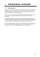
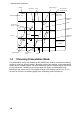
1. OPERATIONAL OVERVIEW Range Coastline Alarm Range Grid 12 NM Display Mode AIS: D HU RM AIS function set for "DISP". Data, menu display area Waypoint Marker 10 Mark AIS Active Target Prohibited Area Route Own Ship Marker Cursor 11 Origin Mark 1.4 Own Ship’s Track Error Message Location Icon Choosing Presentation Mode Five presentation modes are available by the [MODE] key: head-up, head-up true bearing, course-up, north-up, and true-motion.
1. OPERATIONAL OVERVIEW 1.5 Shifting the Display 1.5.1 Shifting by the trackball The display can be shifted by the trackball up to 75% of the range in use in any direction. Operate the trackball to shift the display, and the display shifts in the direction the trackball is operated. When the cursor reaches an edge of the display, the pictures shifts in the opposite direction. 1.5.
1. OPERATIONAL OVERVIEW 1.6 Choosing Chart Scale The chart scale can be selected with the [RANGE+] and [RANGE-] key. A larger range shrinks the picture; a smaller one enlarges it.
2. CHART CARDS NOTICE Chart cards are intended as an aid to navigation. The navigator has the responsibility to check all aids available to confirm position. Handle chart cards and memory cards with care. - Keep cards away from direct sunlight, heat sources, and active gases. - Keep cards away from water and chemicals. - Keep the connector free of foreign material. - Do not drop the cards. 2.1 Displaying Charts 2.1.1 Inserting chart cards 1.
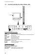
2. CHART CARDS 2.1.2 Chart icons Chart icons are displayed to alert you to chart status. Chart properly displayed. Chart overenlarged. Chart overenlarged or wrong chart. Chart icons 2.1.3 Ejecting chart cards Chart cards may be ejected with the radar turned on or off. 1. Press the EJECT button on the card slot. 3. Remove the chart card. 2.1.4 Troubleshooting • Card inserted but no chart appears. • Small island, etc. not filled in. • Card is removed but chart remains on the screen.
2. CHART CARDS 2.2 Showing/Hiding Chart Features Chart features may be turned on/off as follows: 1. Press the [MENU] key to display the main menu. 2. Press the [1] key twice to show the Video Plot/AIS menu. 3. Press the [9] key twice to choose Coastline/Mark Disp. Coastline/Mark Disp 1. ↑ 2. Waypoint Off On 3. Grid Off On 4. Coast Line Off On 5. Land Density Off On 6. Place Name Off On 7. Lighthouse Off On 8. Lighthouse Data Off On 9. Depth Contour Off On 0.
2. CHART CARDS 5. Press the [ENTER/SELECT] key to register your selection. 6. Press the [MENU] key to escape.
2. CHART CARDS 2.3 Position, Bearing Correction 2.3.1 Position correction There may be some instances where the chart is not overlaid on the radar picture correctly. You can compensate for this error by applying an offset to chart position. Note 1: A gyrocompass is required to get accurate correction. Note 2: The radar display and coastline data use different calculation methods, thus they do not agree. Error is most prevalent in high longitudes. 1. Press the [MENU] key to open the main menu. 2.
2. CHART CARDS 2.3.2 Bearing correction In some cases radar bearing may not match chart bearing. This can be corrected by offsetting bearing, automatically or manually. This feature is useful when no coastline is displayed; that is, vessel is in mid ocean. A magnetic compass is required. 1. Press [MENU], [8], [8], [5], [5] to display the Position Correction menu. 2. Press the [4] key to choose Manu., and press the [ENTER/SELECT] key. 3.
3. TRACK 3.1 Displaying Own Ship’s Track Own ship’s track may be displayed as follows: 1. Press the [MENU] key. 2. Press the [1] key twice to show the Video Plot/AIS menu. 3. Press the [7] key twice to choose Plot Interval. Plot Interval 1. ↑ 2. Own Track Off On 3. Plot Mode Time Dist 4. Plot Time Time = 00M30S 5. Plot Distance Dist = 0.02nm 6. Save Own Track Yes No 7. Other Track* Off On 8. Set Other Plot Intvl* Time = 00M30S 9. Save Other Track* Yes No 0. Plot Color * Function available with ARP-17.
3. TRACK 3.2 Stopping Plotting of Own Ship’s Track When your ship is at anchor or returning to port you probably will not need to plot (record) the track. You can stop plotting the track, to conserve the track memory, by actuating the “HOLD” function. The track is neither plotted nor saved, thereby conserving the track memory. 3.2.1 Stopping track plotting 1. Press [MENU], [1], [1], [7], [7] to display the Plot Interval menu. 2. Press the [6] key to choose No from the Save Own Track field. 3.
3. TRACK 3.3 Changing Own Ship’s Plot Interval The plot interval determines both how the track will be reconstructed on the display and the track storage time. 3.3.1 How the track is drawn The “quality” of the track displayed largely depends on the plot interval setting, smoothing rate, etc. In drawing the track, first the ship’s position fed from the navigation aid is stored into the radar’s memory at an interval of time or distance selected by the operator.
3. TRACK 3.4 Other Ship’s Tracks and Plotting Interval The tracks of up to 20 ships may be displayed when the Auto Tracking Aid ARP-17 is interfaced with the radar. The plotting interval for other ships tracks can be set independently of that for own ship. Also, plotting of other ships tracks may be suspended to conserve track memory. 1. Press [MENU], [1], [1], [7], [7] to display the Plot Interval menu. 2. Press the [7] key twice to choose On from Other Track. 3.
3. TRACK 3.5 Erasing Own Ship’s Track, Other Ship’s Track 3.5.1 Erasing track by percentage You may erase own ship’s track and other ship’s track by percentage points as follows: 1. 2. 3. 4. Press the [MENU] key. Press the [1] key twice to show the Video Plot/AIS menu. Press the [0] key twice to choose AIS/Miscellaneous1. Press the [3] key twice to display the Delete Memory menu. Delete Memory 1. ↑ 2. Mark No Display All 3. Own Track No 30% 50% 80% All 4. Target Track No 30% 50% 80% All 5.
3. TRACK 3.5.2 Erasing track by color Own ship’s track and target tracks may be erased by color as follows: 1. Press [MENU], [1], [1], [0], [0], [3], [3] to show the Delete Memory menu. 2. Press the [5] key (Own Track Color All) or [6] (Target Track Color All) depending on your objective. 3. Press the [ENTER/SELECT] key. 4. Press the [ENTER/SELECT] key again followed by the [MENU] key. 3.
4. MARKS, LINES 4.1 Displaying Marks, Lines 4.1.1 Displaying marks, lines on the radar display 1. Press the [MENU] key. 2. Press the [8] key twice to show the Mark menu. 1. Mark Selection = 01 01 03 05 07 09 11 13 15 16 Nav Line --17 Coastline __ 18 Depth Contour --19 Prohibited Area 20 Cable 21 Erase Mark 02 04 06 08 X 10 12 14 2. Display On Off 3. Erase No Erase Display Erase All 4. Entry Method Cursor L/L OS Position 00°00.000’N 000°00.000’E 5.
4. MARKS, LINES 4.1.2 Displaying marks, lines on the combination and video plotter displays 1. Press the [MENU] key. 2. Press the [8] key twice to show the Mark menu. Plotter Mark 1. Mark Selection = 01 01 Origin Mark 02 OS Position 03 04 05 06 07 08 09 10 X 11 12 13 14 15 16 − 17 18 Prohibited Area 19 Cable 20 Erase Mark 2. MOB 3. Display On Off 4. Mark Color* R Y G C M B W 5. Position Correction * For the IMO-type radar the choices are RED, PNK (pink), PPL (purple) and ORG (orange).
4.2 Entering Marks, Lines You can inscribe marks and lines on the display to denote important locations such as fishing spots, buoys, islands, etc. 4.2.1 Entering marks on the radar display Choosing mark entry method Marks may be entered on the radar display by cursor, latitude and longitude position and own ship’s position. 1. 2. 3. 4. 5. 6. Press the [MENU] key. Press the [8] key twice to display the Mark menu. Press the [1] key to choose Mark Selection.
4. MARKS, LINES 4.2.2 Entering marks on the combination, video plotter displays Marks can be entered on the combination and video plotter displays by cursor or at own ship’s position. Choosing mark type 1. 2. 3. 4. 5. Press the [MENU] key. Press the [8] key twice to display the Mark menu. Press the [1] key to choose Mark Selection. Use the numeric keys to enter mark or line number desired. Press the [ENTER/SELECT] key.
4. MARKS, LINES 4.3 Erasing Marks, Lines 4.3.1 Erasing individual marks and lines 1. For mark, place the cursor on mark to erase. For line place the cursor on the point to erase. 2. Press the [CANCEL/CLEAR] key. If the mark is not erased it may superimposed on several marks. In this case, press the [CANCEL/CLEAR] key several times. To erase an entire line, all its points must be erased. Individual origin marks and EPA plotting symbols are also erased in the same manner as marks and lines.
4. MARKS, LINES 4.4 MOB Mark The MOB (Man Overboard) mark denotes position of man overboard. This mark can only be inscribed on the combination and video plotter displays. Range and bearing Inscribe MOB mark immediately when man is overboard. Current position MOB mark M MOB concept 1. Press the [MENU] key. 2. Press the [8] key twice. 3. Press the [2] key to choose 2. MOB. The MOB mark (“M”) is inscribed at own ship’s position the moment the key is pressed. 4. Press the [MENU] key to close the menu.
4. MARKS, LINES 4.5 Origin Mark The origin mark ( ) is mainly used to find the range and bearing between two targets on the radar/plotter and plotter displays. 1. 2. 3. 4. 5. 6. 7. 8. Press the [MENU] key. Press the [8] key twice to display the Mark menu. Press the [1] key to choose Mark Selection. Enter [0], [1] to choose Origin Mark . Press the [ENTER/SELECT] key. Place the cursor on target and press the [MENU] key. Place the cursor on the other target. Press the [MARK] key to close the menu.
5. WAYPOINTS, ROUTES In navigation terminology, a particular location is known as a “waypoint,” whether it be a starting point, a destination point or an intermediate point on a voyage. 5.1 Turning Waypoints On/Off You may choose to turn all waypoints on or off, and the default setting is ON. Note however that when a route is displayed its waypoints are shown regardless of whether waypoints are turned on or off. 1. 2. 3. 4. 5. Press the [MENU] key.
5. WAYPOINTS, ROUTES 5. Press the [3] key (OS Pos) twice, and a waypoint mark with waypoint number inside is inscribed at own ship’s position. 6. Press the [MENU] key to finish. If there is no empty waypoint, a beep sounds and no waypoint can be entered. In this case erase unnecessary waypoints. 5.2.2 Entering waypoints at cursor position 1. Press [MENU], [1], [1], [4], [4]. 2. If you want to register the waypoint under a number different from what is shown below “WPT No.
5. WAYPOINTS, ROUTES 3. Operate the trackball to place the cursor on an empty waypoint. You can scroll the list by placing the cursor at the bottom of the page. 4. Key in latitude and longitude with the numeric keys. Note: You can switch from North to South, East to West and vice versa with the [-] key. Do this before entering the data. An entire line of data can be cleared with the [CANCEL/CLEAR] key.) 5. If you want to enter a comment follow the procedure below. If not, go to step 6.
5. WAYPOINTS, ROUTES 5.4 Creating Routes In many cases a trip from one place to another involves several course changes, requiring a series of route points (waypoints) which you navigate to, one after another. The sequence of waypoints leading to the ultimate destination is called a route. The RP-180 can automatically advance to the next waypoint on a route, so you do not have to change the destination waypoint repeatedly.
5. WAYPOINTS, ROUTES 10. As the screen prompts, place the cursor where you want to have a waypoint for the route. 11. Press the [+] key. (To clear just-selected point, press the [-] key.) 12. Repeat steps 10 and 11 to complete the route. 13. Press the [ENTER/SELECT] key to register the route and the [MENU] key to close the menu. 5.4.2 Creating routes with waypoints 1. 2. 3. 4. Press [MENU], [1], [1], [5], [5] to display the Route menu. Press the [1] key to choose WPT no.
5. WAYPOINTS, ROUTES 5.4.3 Creating routes from the route list 1. 2. 3. 4. Press [MENU], [1], [1], [5], [5] to display the Route menu. Press the [1] key to choose List, and press the [ENTER/SELECT] key. Press the [2] key to choose Speed for TTG. Key in ship’s speed with the numeric keys. (This allows for automatic calculation of time-to-go to waypoints.) 5. Press the [ENTER/SELECT] key. 6. Choose route number with the trackball. 7. Press the [ENTER/SELECT] key.
5. WAYPOINTS, ROUTES 5.5 Turning Route Display On/Off You may choose to display (or not) a route as follows. 1. 2. 3. 4. 5. 6. Press the [MENU] key. Press the [1] key twice to show the Video Plot/AIS menu. Press the [5] key twice to choose Route. Choose route number with the trackball. Press the [ + ] key to display the route; the [ - ] key to not display it. Press the [ENTER/SELECT] key to register your selection and the [MENU] key to close the menu.
5. WAYPOINTS, ROUTES 5.6 1. 2. 3. 4. 5. 6. 7. 8. 9. Press [MENU], [1], [1], [5], [5] to display the Route menu. Press the [1] key twice to choose List. Press the [ENTER/SELECT] key. Use the trackball to choose route number. Press the [ENTER/SELECT] key. Use the trackball to choose route waypoint to delete. Press the [CANCEL/CLEAR] key. Press the [ENTER/SELECT] key. The route data changes to reflect deletion. Press the [MENU] key to finish. 5.7 1. 2. 3. 4. 5.
6. NAVIGATION This section covers navigation. You can navigate by waypoint, cursor-selected point and route. 6.1 Navigation 6.1.1 Navigating to a waypoint 1. Press the [MENU] key. 2. Press the [1] key twice to show the Video Plot/AIS menu. 3. Press the [6] key twice to choose Destination Set. Destination 1. ↑ 2. Destination Set Cancel 3. Mode Cursor WPT Route No. MOB Destination set menu 4. Press the [3] key to choose Mode. 5. Press the [3] key again to choose WPT.
6. NAVIGATION 6. Press the [ENTER/SELECT] key. Destination Set WPT Nos. = - -+- -+- -+- -+ -+- -+- -+- -+- -+- - -+- -+- -+- -+ -+- -+- -+- -+- -+- -+- - -+- -+- -+- -+ -+- -+- -+- -+- -+- -+- - (Waypoint List) No. ↑ u 1 00°00.000'N 000°00.000'E 2 00°00.000'N 000°00.000'E 3 ° . 'N ° . 'E 99 ° . 'N ° . Comment ABCDEFGHJK 9876543210 'E Select WPT and press + key. To cancel, press - key. Screen for entry of destination waypoints 7. Use the trackball to choose a waypoint.
6. NAVIGATION 6.1.3 Following a route 1. Press [MENU], [1], [1], [6], [6] to display the Destination menu. If a route is currently selected as destination, its number is shown at the top of the screen. 2. Press the [3] key to choose Route No. and press the [ENTER/SELECT] key. 3. Confirm that Route No. is selected. 4. Press the [ENTER/SELECT] key, and your display now looks something like the one below. Destination Set 1. Route nos. = 2. FWD/REV = Forward Reverse (Route List) No.
6. NAVIGATION 6.2 Cancelling Navigation Once you arrive at your ultimate destination you probably won’t need the destination waypoint. You can cancel it as follows: 1. Press [MENU], [1], [1], [6], [6] to display the Destination menu. 2. Press the [2] key to choose Cancel. 3. Press the [ENTER/SELECT] key followed by the [MENU] key. Note: MOB destination can also be cancelled by placing the cursor on the MOB mark and pressing the [CANCEL/CLEAR] key.
6. NAVIGATION Display "Yes" to skip waypoint. Route u (No. 01) WPT Skip Distance TTG 1 2 3 4 5 6 7 8 9 10 08 11 15 18 22 ------ YES NO YES NO NO NO NO NO NO NO 0.0 nm 0.0H 135.67 nm 75.6H 185.07 nm 125.6H 234.60 nm 234.6H 258.67 nm 345.6H - - -.- - nm - - - - -.- - H - - -.- - nm - - - - -.- - H - - -.- - nm - - - - -.- - H - - -.- - nm - - - - -.- - H - - -.- - nm - - - - -.- - H 30 -- NO - - -.- - nm - - - - -.- - H Move cursor and enter WPT no.
6. NAVIGATION (This page intentionally left blank.) .
7. ALARMS There are four conditions which releases visual and audible alarms: Arrival alarm, Anchor watch alarm, XTE (Cross-track Error) alarm and Border alarm. When an alarm setting is violated the audible alarm sounds and the alarm icon ( ) appears at the bottom right-hand corner of the display. To silence the buzzer, press the [AUDIO OFF] key. 7.1 Arrival Alarm, Anchor Watch Alarm The Arrival alarm alerts you when own ship nears a waypoint by the distance set.
7. ALARMS Before setting the arrival or anchor watch alarm, set a destination waypoint. For the anchor watch alarm the destination should be own ship position. 1. 2. 3. 4. Press the [MENU] key. Press the [1] key twice to show the Video Plot/AIS menu. Press the [0] key twice to choose Miscellaneous. Press the [2] key twice to choose Alarm Set. Alarm Set 1. ↑ 2. Arrival/Anchor Arrival Anchor Off Alarm Range 1. 000 nm 3. XTE/Border XTE Border Off Alarm Range 1.
7. ALARMS 7.2 XTE Alarm, Border Alarm The XTE (cross-track error) alarm warns you when own ship is off its intended course. The Border alarm alerts you when own ship is nearing an area which you do not want to approach. Own ship position Alarm setting Destination waypoint Intended course : Alarm XTE ALARM Setting line Alarm setting : Alarm range Own ship's position BORDER ALARM 1. 2. 3. 4. 5. 6.
7. ALARMS This page intentionally left blank.
8. MEMORY CARD OPERATIONS 8.1 Formatting Memory Cards Before you can save information to a memory card you must prepare its surface by formatting it. Formatting is a routine procedure you must perform on new cards before you can use them with this unit. You have to initialize them only once. You can format cards you’ve used before, however, in which case all prior information on them is erased. 1. Press the [MENU] key. 2. Press the [1] key twice. 3. Press the [8] key twice to open the Memory Card menu.
8. MEMORY CARD OPERATIONS 4. Press the [2] key twice to open the Save Data menu. Save Data 1. 2. MarklLine 3. WPTlRoute 4. Track (Own Ship) 5. Track (Targets) 6. Mark (RadarMap) 7. Initial Setting 8. Delete Card Data 9. Format 0. Save Data menu 5. Press the [9] key twice to choose Format. 6. As the screen prompts, press the [ENTER/SELECT] key to format the card. “Formatting” appears while the card is being formatted, and “Formatting completed” when formatting is completed. 7.
8. MEMORY CARD OPERATIONS 8.2 Saving Screen Contents to Memory Card The memory cannot store track and marks indefinitely. For this reason, important track and marks should be saved to a memory card. A memory card can store 50 files. For 6,000 track points, for example, the card can store eight files (card memory capacity: 512 KB). 1. 2. 3. 4. Insert a formatted memory card in the card slot. Press [MENU], [1], [1], [8], [8] to display the Memory Card menu.
8. MEMORY CARD OPERATIONS 6. Assign a file name as below. A file name may contain 32 alphanumeric characters. For example, assign the file name FURUNO1. (a) Choose the character “F” with the trackball. (b) Press the [ENTER/SELECT] key. (You can change a wrong character by choosing it with the trackball and the entering correct character. You may cancel an entire line of data with the [CANCEL/CLEAR] key.) (c) Choose the character “U” with the trackball and press the [ENTER/SELECT] key.
8. MEMORY CARD OPERATIONS 8.3 Displaying Memory Card Contents on the Display Up to eight files may be played back on the radar display. 1. Insert memory card in card slot. 2. Press [MENU], [1], [1], [8], [8] to display the Memory Card menu. 3. Press the [3] key twice to choose Display Card Data. Display Card Data (L SLOT) Disp u01 1234567890123456 7890123456789012 02 Aimee (2004-03-27) MARK 44 (2004-03-27) WPT 13 YES NO NO 03 10 (TOTAL NO.
8. MEMORY CARD OPERATIONS 8.4 Playing Back Memory Cards Memory card contents can be played back on the screen. This feature is useful for editing and copying card contents. 1. Insert memory card in card slot. 2. Press [MENU], [1], [1], [8], [8] to display the Memory Card menu. 3. Press the [4] key twice to choose Play Back Data. Play Back Data 1. 2. MarklLine 3. WPTlRoute 4. Track (Own Ship) 5. Track (Targets) 6. Mark (RadarMap) 7. Initial Setting 8. 9. 0. 4. 5. 6. 7.
8. MEMORY CARD OPERATIONS 8.5 Erasing Files from Memory Cards You can erase unnecessary files as follows: 1. Press [MENU], [1], [1], [8], [8] to display the Memory Card menu. 2. Press the [2] key twice to choose Save Data. 3. Press the [8] key twice to choose Delete Card Data. Delete Card Data (L SLOT) u01 1234567890123456 02 Aimee Date (2004-04-10) Pts. 1234 MARK (2004-03-27 1234 WPT 03 04 05 06 10 (TOTAL NO. OF FILES = 02) Move cursor by using trackball and press ENT. Escape: MENU 4. 5. 6. 7.
8. MEMORY CARD OPERATIONS (This page intentionally left blank.
9. OTHER FUNCTIONS 9.1 Entering Ship’s Position Manually Ship’s speed is normally input by the navigator connected to the radar. If the navigator fails enter ship’s position manually as follows: 1. 2. 3. 4. Press the [MENU] key. Press the [1] key twice to show the Video Plot/AIS menu. Press the [0] key twice to choose AIS/Miscellaneous1. Press the [7] key twice to choose Miscellaneous2. MIscellaneous2 1. ↑ 2. Pos. Sensor Navaid Manual 3. Own Ship Pos. 00°00.000'N 000°00.000'E 4.
9. OTHER FUNCTIONS 9.2 Smoothing Own ship’s track may be traced on the screen with a crooked line even though the ship is running straight. This is due to navaid signal variation, and can be compensated by adjusting the smoothing factor. A smoothing setting between 00 and 15 is available. The higher the figure the more the track is smoothed however too high a setting slows response time to speed and course changes. 1. Press [MENU], [1], [1], [0], [0], [5], [5] to display the Initial Setting menu.
9. OTHER FUNCTIONS 9.4 Adjusting Brilliance 9.4.1 Chart features You may adjust the brilliance of chart features as follows: 1. Press [MENU], [9], [9], [9], [9] to display page 2 of the Brill menu. PLOTTER BRIL 1. ↑ 2. LAND 3. GRID 4. MARK 5. CONTOUR 6. COLOR Brill menu, page 2 2. Press appropriate numeric key among 2-5 to choose item to change brilliance. 3. Use the VRM control to adjust brilliance. Watch the bar graph to judge brilliance level. The range of the bar graph is 10% to 100%. 4.
9. OTHER FUNCTIONS 9.5 Clearing All Data You may clear all track, marks, waypoints and routes to start afresh. 1. 2. 3. 4. 5. 6. 7. Press the [MENU] key. Press the [1] key twice to show the Video Plot/AIS menu. Press the [0] key twice to choose AIS/Miscellaneous1. Press the [7] key twice to choose Miscellaneous2. Press the [5] key twice to choose Delete Data. Press the [ENTER/SELECT] key.. Press the [MENU] key to finish. 9.6 1. 2. 3. 4. 5. 6. 7. 8. Restoring Default Settings Press the [MENU] key.
9. OTHER FUNCTIONS 9.7 Marker Colors on Chart Cards You may change the color of grid, marks, land and depth contour as follows. 1. Press [MENU], [9], [9], [9], [9], [6], [6] to display the Plotter Color menu. PLOTTER COLOR 1. ↑ 2. MARK R Y G C M B W 3. GRID R Y G C M B W 4. LAND R Y G C M B W 5. CONTOUR R Y G C M B W Plotter Color menu 2. Press appropriate numeric key to choose marker and color desired. R, Red; Y, Yellow; G, Green; C, Cyan (Light-blue); M, Magenta; B, Blue, W, White. 3.
9. OTHER FUNCTIONS 9.8 Apportioning the Memory The memory holds a total of 40,000 points of tracks and marks, and the default memory apportion is 20,000 points each of tracks and marks. However, you may change that setting to suit your operating needs as follows: Note: All track and marks are erased when the memory is reapportioned. 1. 2. 3. 5. Press the [MENU] key. Press the [1] key twice to show the Video Plot/AIS menu. Press the [0] key twice to choose AIS/Miscellaneous1.
10. AIS The AIS (Automatic Identification System) feature automatically provides navigation data on AIS-equipped ships. WARNING Confirm compass reading on radar and gyrocompass readout when the bearing of AIS targets do not match that of corresponding radar targets. 10.1 Changing Function of [F2] Key to AIS If desired the [F2] can be programmed to open the AIS(1) menu. 1. 2. 3. 4. 5. 6. 7. Press the [STBY/TX] key to set the radar in stand-by. Press the [MENU] key.
AIS 10.2 Turning AIS Feature On/Off 1. Press the [F2] key to open the AIS(1) menu. [AIS(1)] 1. Activate Target 2. Sleep Target 3. Basic Data 4. [Extended Data] 5. Lost Target 6. [Message] 7. Activate All Targets 8. Sleep All Targets 9. AIS Off Func Disp 0. [AIS(2)] AIS(1) menu 2. Press the [9] key to choose Off, Func, or Disp as appropriate. Off: All AIS symbols erased and the AIS function is deactivated. Func: All AIS symbols are erased, but all other AIS functions (collision watch, etc.
AIS 10.3 Activating Targets 1. Use the trackball to place the cursor on the sleeping AIS target (indicates only the presence of a vessel equipped with AIS in a certain location) you wish to activate; that is, know more about a vessel’s motion. 2. Press the [F2] key to open the AIS(1) menu. 3. Press the [1] key (Activate Target) to activate the target. The activated AIS target symbol is superimposed on the radar echo as below.
AIS 10.4 Sleeping Targets 10.4.1 Sleeping specific AIS target You may “sleep” an AIS target as below when the screen becomes filled with targets. Note that targets that have been activated automatically cannot be “slept.” 1. 2. 3. 4. Use the trackball to place the cursor on an activated AIS target symbol. Press the [F2] key to open the AIS(1) menu. Press the [2] key (Sleep Target) to sleep the target. Press the [MENU] key to close the menu.
AIS 10.5 Displaying Target Data 10.5.1 Basic target data 1. Place the cursor on an AIS target symbol. 2. Press the [ENTER/SELECT] key to show the target’s basic data. The target is marked as below. Activated target selected for data display AIS target, fusion target no. Call sign Bearing from own ship to target Range from own ship to target Course over ground Speed over ground CPA TCPA AIS 02 TRUE VECT 1436782 6min BT BRG 234.1° T RNG 9.92NM COG* 321.2° T BT SOG# 21.1KT BT CPA 2.
AIS 10.5.2 Extended target data 1. With basic data displayed as in paragraph 10.5.1, press the [F2] key to open the AIS menu. 2. Press the [4] key (Extended Data) to display the selected target’s extended data. Ship’s name Call sign Latitude Longitude Heading Rate Of Turn Position-fixing device Position accuracy (High, Low) Navigation status MMSI No. IMO No. Length Width Draft Destination Estimated Time of Arrival Fusion (AIS and ARPA combined) target no. Type of ship and cargo [Extended Data] 1.
AIS 10.6 Lost Target A target is declared a lost target when no data is received for three to five reporting intervals. When this occurs, the target is marked with the (flashing) lost target symbol and the indication “A-LOST” appears. Press the [CANCEL/CLEAR] key to acknowledge the lost target, and the lost target disappears. However, the target which becomes a lost target is a activated target or a sleeping target within the lost target range. (See paragraph 10.11.
AIS 3. Press appropriate numeric key among 2-5 to choose the type of message you want to see. The example below shows a safety related message (addressed).
AIS 10.8 History Display The history display shows equally time-spaced dots marking past positions of activated targets being tracked. A new dot is added at preset time intervals until the preset number is reached. If a target changes its speed, the spacing will be uneven. If it changes course, its plotted course will not be a straight line. Below are sample history displays. (a) Ship turning (b) Ship running straight (c) Ship reduced speed (d) Ship increased speed Sample history displays 10.8.
AIS 10.8.2 Choosing history display attributes You may choose history point color, the number of history points to show per history plot interval and the history plot interval as below. Note that the color of the history points is the same as the symbol color. 1. 2. 3. 4. 5. 6. 7. 8. 9. Press the [F2] key to open the AIS(1) menu. Press the [0] key twice to show the AIS(2) menu. Press the [3] key (History Points).
AIS 10.10 Automatic Target Activation You may automatically activate all targets within a specific distance from own ship as below. Note that you may also automatically activate all targets within the ARPA’s automatic acquisition zone or guard zone. When a target enters the ARPA’s automatic acquisition zone or guard zone, it is automatically marked with the activated target symbol. If the activated target goes out of the ARPA automatic acquisition zone or the guard zone it still is an activated target.
AIS 10.12 ROT Display Setting You may set the lower limit of the ROT (Rate Of Turn) at which the heading line on target symbols will point in direction of turning. 1. 2. 3. 4. 5. 6. Press the [F2] key to open the AIS(1) menu. Press the [0] key twice to show the AIS(2) menu. Press the [6] key (ROT Tag). Use the numeric keys to enter ROT (000.1 to 720.0°/min). Press the [ENTER/SELECT] key. Press the [MENU] key to close the AIS menu.
AIS 10.13 Combining AIS with ARPA (fusion) If equipped with ARPA it may be jointly used with the AIS. In this case specify the parameters for which an ARPA target is converted to an AIS target. 1. 2. 3. 4. Confirm that "MAN" or “AUTO+MAN” is shown at the right-hand corner of the display. Press the [F2] key to open the AIS(1) menu. Press the [0] key twice to open the AIS(2) menu. Press the [0] key twice to open the AIS(3) menu. [(AIS(3)] 1. 2. Fusion On Off Posn 0.000NM Rng 0.000NM Brg 00.0° Spd 0.
AIS 10.14 AIS System Messages AIS system messages are displayed at the bottom right corner of the screen. The table below shows the AIS system messages and their meanings. AIS system messages Message A-FSN A-CLSN A-LOST A-RCV A-WT A-GZ A-CPA A-FULL 10-14 Meaning ARPA target converted to AIS target. The indication disappears when the target no longer meets the criteria set for the fusion feature. When the message A-RCV is displayed, A-FSN not displayed. CPA/TCPA of an AIS target is below preset value.
BT WT BT BT ON OFF/ ON LOG NAV LOG OFF/ (S-BT) ON LOG OFF (S-WT) LOG ON (S-WT) REF BT WT Target based speed VTG VTG BT data of VBW VTG VTG VTG VTG VTG BT WT data of VBW Log Pulse MAN WT Own ship speed data (Note 3) Target based course VTG VTG BT data of VBW and Gyro calculation VTG VTG VTG VTG VTG BT BT data of VBW and gyro calculation GYRO GYRO WT Own ship course data (Note 3) A-CPA LOG LOG Log Pulse A-CPA A-WT A-CPA A-CPA LOG A-CPA A-WT A-CPA A-CPA A-WT
AIS 10.15 AIS Alarm Message The AIS(3) menu provides AIS alarm message information ($AIALR sentence) from the AIS transponder. When an AIS alarm message is received “A-ALM” appears at the bottom right-hand corner of the screen.
11. MAINTENANCE, TROUBLESHOOTING 11.1 Replacement of Batteries The battery icon ( ) appears on the display when the voltage of the memory card battery or the battery on the RP Board is low. To find out which battery it is, conduct the diagnostic test as described in Paragraph 11.2. “NG” appears as a battery check results when battery voltage is low. Replace the battery at your earliest convenience. The life of the both batteries is about three years.
11. MAINTENANCE, TROUBLESHOOTING 11.2 Diagnostic Test 1. 2. 3. 4. Press the [MENU] key. Press the [1] key twice to show the Video Plot/AIS menu. Press the [0] key twice to choose AIS/Miscellaneous1. Press the [6] key twice to choose Test. The diagnostic test displays program version no., checks the ROM, RAM, DPRAM, SRAM, internal battery, memory card battery and serial input(*2) for proper operation, displaying OK or NG (No Good) as the check result.
12. INSTALLATION 12.1 Necessary Parts Contents of RP-180 installation kit Name Type Qty Code No. Floppy Disk NO.03591521XX 1 RP Board 14P0390A 1 Cable Assy. 03S9456 1 000-142-369 Label (M-card) 03-134-9106 1 100-235-230 Pan Head Screw M3x8 C2700W 5 000-881-404 Toroidal Core TFC-25-15-12A 1 000-145-474 Cable Tie CV-150N 1 000-570-325 Clamp CK-05H 1 000-570-247 Shrink Tubing 3x0.25 0.1m 1 000-105-874 NH Connector Assy.
12. INSTALLATION 12.2 Installation 1. 2. 3. 4. Turn off the display unit power switch. Turn off all equipment connected to the radar. Open the card slot cover at the left front of the display unit. Attach label as shown below. Label (M-card) 03-134-9106 LOT CARD S Attachment of labels 5. Unfasten eight screws to remove the cover. 6. Fasten the RP Board with five panhead screws.
12. INSTALLATION 7. Connect the cable assy. between J106 on the SPU Board and J3 on the RP Board. Attach toroidal core to cable assy. and fasten cable assy. with cable tie. Cable Assy. 03S9456 P4 J3 RP Board 14P0390A J4 (Connector for updating program, option) B J2 (Connector for AIS) J3 Panhead Screw M3X8 (5 pcs.) Cable Tie CV-150 SPU BOARD 03P9230 J106 SPU chassis Toroidal Core TFC-25-15-12 A FRONT PANEL RP Board TOP VIEW LEFT SIDE Chassis Square Bushing Toroidal Core Face notch upward.
12. INSTALLATION 8. To connect the AIS transponder, connect the NH connector assy. (5P) to J2, routing the cable as shown below. To J2 on RP Board Square Hole Attach clamp (supplied) and pass through clamp. J101 J103 SPU Board 03P9230 J105 J104 30 mm Align flush with chassis. Pass through clamp.
12. INSTALLATION 10. Turn on the radar and conduct the self test by pressing [MENU], [0], [0], [0], [0], [2], [2]. Check the radar program number, at the top of the screen. If it is younger than the program number recorded on the floppy disk (supplied), the program must be updated. If updating is not required, no further adjustment is necessary; turn off the radar. FR-1500 M-3 SERIES TEST 1. Program No. 03591521XX* 2. ROM Check OK EPA OK 3. RAM Check OK 4. Antenna Rotation rpm 5.
12. INSTALLATION 11. If necessary, update the program as follows: a) Connect the PC connection cable between the serial port (D-SUB 9 pin) on the PC and J304 on the MAIN PANEL Board of the radar. Remove rubber cap under front panel and connect XH4P connector. PC FR-1500 MKIII Series SERIAL PORT TX RS232C RX RS232C GND J304 MAIN PANEL Board (03P9226) 3 2 5 4 6 7 8 1 2 3 4 RD-DT TX-DT GND N.C.
APPENDIX 1. Digital Interface Input sentences (RP board, J2) VDM, ALR, VDO Data reception Data is received in serial asynchronous form in accordance with the standard referenced in IEC 61162-2. The following parameters are used: Baud rate: 38400, Data bits: 8 (D7 = 0), Parity: none, Stop bits: 1 D0 D1 Start bit D2 D3 D4 Data bits D5 D6 D7 Stop bit Data sentences ALR –Set alarm state $AIALR,hhmmss.
APPENDIX VDM – VHF data-link message !AIVDM,x,x,x,a,s--s,x*hh | || | | | | | | | | | | +----- 7 | | | | | +----- 6 | | | | +-------- 5 | | | +------------ 4 | | +-------------- 3 | +---------------- 2 +------------------ 1 1. Total number of sentences needed to transfer the message, 1 to 9 2. Message sentence number, 1 to 9 3. Sequential message identifier, 0 to 9 4. AIS channel Number 5. Encapsulated ITU-R M.1371 radio message 6. Number of fill-bits, 0 to 5 7.
APPENDIX Schematic diagram Load requirements as listener 2.
APPENDIX 2.
APPENDIX 4. Menu Tree The example screens shown in this manual may not match the screens you see on your display. The screen you see depends on your system configuration and equipment settings. Video plotter menu [MENU] key 1. Radar Disp 2. Combination Disp 3. Video Plot Disp* 1. VIDEO PLOT/ AIS 4. Waypoint 5. Route 6. Destination Set 7. Plot Interval 8. Memory Card 1. Default settings 2. Cursor in bold italics. 3. OS Pos. 4. List 5. WPT No. (01 - 98) 1. Mode (Cursor, WPT No., List) 2.
APPENDIX 2 1 9. Coastline/Mark Disp 0. AIS/ Miscellaneous1 2.TGT TRAIL 1. 2. Waypoint (Off, On) 3. Grid (Off, On) 4. Coast Line (Off, On) 5. Land Density (Off, On) 6. Place Name (Off, On) 7. Lighthouse (Off, On) 8. Lighthouse Data (Off, On) 9. Depth Contour (Off, On) 0. Plotter Presentation (Default, User set) 1. 2. Alarm Set 1. 2. Arrival/Anchor (Arrival, Anchor, Off) Alarm Range (0.001 - 9.999nm, 0.5nm) 3. XTE/Border (XTE, Border, Off) Alarm Range (0.001 - 9.999nm, 0.25nm) 1. 2.
APPENDIX 3 8. MARK Radar Display Radar/Video Plotter Combination Display, Video Plotter Display 1. Mark Selection (01 - 21) 2. Display (On, Off) 3. Erase (No, Erase Display, Erase All) 4. Entry Method (Cursor, L/L, OS Position) 5. Position Correction 1. 2. Position Corr. 1. Mark Selection (01-20, 03) (No, Yes) 2. MOB 3. Delta L/L Entry 3. Display (On, Off) * 4. Variation 4. Mark Color (Off, Manu, Auto) (IMO spec.: Red, Pink, Purple, Orange Non-IMO type: Red, Yellow, Green, Cyan, Magenta, Blue, White) 5.
APPENDIX AIS menu 4 [F2] key (programmed to display AIS(1) menu) 1. Activate Target 2. Sleep Target 3. Basic Data 4. [Extended Data] 5. Lost Target 6. [Message] 7. Activate All Targets 8. Sleep All Targets 9. AIS (Off, Func, Disp) 0. [AIS(2)] AP-8 1. (Detailed data on target selected) 1. 2. Safety Related Message (Addressed) 3. Safety Related Message (Broadcast) 4. Binary Message (Addressed) 5. Binary Message (Broadcast) 6. (Auto Display (On, Off) 1. 2. History (On, Off) 3.
APPENDIX 5. Chart Icons • Wrong chart card inserted. • Chart overshrunk. • Chart overenlarged. • Data reliability is low. • Chart properly displayed; full accuracy. • Chart offset applied. • Alarm setting violated. • Icon disappears when alarm is disabled. • Voltage of battery on circuit board or memory card is low. H • Track recording/plotting suspended. • Appears while screen is being redrawn.
APPENDIX (This page intentionally left blank.
FURUNO RP-180 SPECIFICATIONS OF VIDEO PLOTTER RP-180 1 GENERAL 1.1 Display Display of FR-1500 MK3 series Radar 1.2 Display Mode Radar picture overlaid on plotter picture 1.3 Presentation Mode North up (NU), True motion (TM), Course up (CU), Head up (HU), Cursor Gyro (CG) 1.4 Display Range 0.125/0.25/0.5/0.75/1/1.5/2/3/4/6/8/12/16/24/34/48/72 (nm) 1.5 Projection Mercator 1.6 Usable-Latitude 80° or below 1.6.1.1.1 Coastline Data 1.
INDEX A AIS activating targets....................................10-3 basic target data ....................................10-5 dangerous targets..................................10-3 extended target data..............................10-6 F2 key ....................................................10-1 lost target ...............................................10-7 messages, automatic display ................10-8 messages, manual display ....................10-7 on/off .....................................
INDEX O Offcentering .................................................1-3 Origin mark ..................................................4-7 P Presentation mode ......................................1-2 R Routes creating from route list.............................5-6 creating with cursor .................................5-4 creating with waypoints ...........................5-5 deleting route waypoints..........................5-8 routes.......................................................