
Owner's Manual


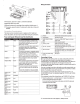


Table Of Contents

3
Select
an
option:
Connect
the
yellow
wire
to
the
positive(+)
battery
terminal,
and
route
the
red
signal
wire
@
to
the
ignition
or
another
manual
switch
@.
•
Connect
the
yellow
wire
to
the
red,
and
connect
them
to
the
positive(+)
battery
terminal.
Speaker
Zones
You
can
group
speakers
in
one
area
into
speaker
zones.
You
can
then
control
the
audio
level
of
the
zones
individually.
For
example,
you
might
want
the
audio
quieter
in
the
cabin
and
louder
on
deck.
You
can
set
the
balance
,
volume
limit
,
subwoofer
level,
and
name
for
each
of
the
available
zones.
Up
to
two
pairs
of
speakers
can
be
connected
per
zone
in
parallel
to
increase
the
amplifier
output.
Subwoofer
Amplifier
Connection
Considerations
This
stereo
supports
output
to
a
powered
subwoofer
from
all
zone
outputs.
The
subwoofer
port
on
the
stereo
outputs
a
mono
line-level
signal.
The
port
output
audio
level
is
linked
to
the
zone
.
•
You
should
connect
the
connectors
to
the
included
splitter.
•
You
need
a
splitter
for
each
zone.
One
splitter
is
included.
Speaker
Amplifier
Connection
Considerations
In
add
i
tion
to
the
two
stereo
speaker
zones
available
through
the
wiring
harness,
this
stereo
can
be
connected
to
multiple
amplifiers
through
zone
connections.
•
The
blue
wire
from
the
wiring
harness
must
be
connected
to
the
amplifier
to
provide
a
signal
to
turn
on
the
amplifier
with
the
stereo
.
If
it
is
necessary
to
extend
this
blue
signal
wire
,
use
22
AWG
(0.33
mm
2
)
wire.
•
The
audio
output
is
a
stereo
line
level
ou
tput
over
standard
RCA
cable
.
Common
Connections
to
the
Stereo
You
can
connect
a
variety
of
additional
media
inputs
and
outputs
to
the
stereo,
depending
on
the
stereo
model
and
the
devices
to
which
you
are
connect
i
ng.
The
connectors
are
color
coded
to
assist
you
in
making
the
correct
connections
.
For
example
,
your
TV
may
have
an
HOM
I
connector.
Connect
the
HOM
I
cable
to
the
HOM
I
connector
on
the
stereo
.
This
table
lists
some
possible
ways
to
connect
devices
to
the
stereo
.
NOTE:
Not
all
connectors
are
ava
i
lable
on
all
stereo
models.
Input
Stereo
Connections
FM
/
AM
radio
antenna'
Antenna
connecto
r
Siriu
s
XM
Connect
Tuner
ACCESSORY
USB
device
USB
conne
c
tor
or
th
e
built-in
do
ck
(UD
mode
ls)
TV
with
a
co
mp
osite
video
Yellow
to
COMPOSITE
VIDEO
(MS
-
650AV
o
nl
y)
conn
ec
tor a
nd
RCA
a
udio
line
RCA
line
out
s
from
TV
to
AUX
IN
1
or
AUX
IN
2
outs
TV
with
component
co
nnectors
Three
c
omponent
video
connector
s
to
match
in
g
and
RCA
audio
line
outs
connectors
on
stereo
(MS
-
650AV
only)
RCA
line
outs
from
TV
to
AUX
IN
1
or
AU
X
IN
2
TV
with
an
HOM
I
connector
HOM
I
(MS-750AV
o
nly)
*
Metal
hull
vesse
ls
should
use
a
marine
,
AM/FM
,
ground
-
dependant
antenna.
Other
vessels
can
use
a
marine,
AM/FM
,
ground-independent
antenna.
Audio
Return
Channel
The
Audio
Return
Channel
(ARC)
enables
you
to
play
the
audio
from
the
telev
i
sion
over
the
stereo
system
speakers
.
ARC
elim
i
nates
the
need
to
connect
a
separate
audio
cable
from
the
HDMI
television
to
the
stereo.
Typically,
in
televisions
without
ARC,
to
play
the
audio
from
the
television
over
the
stereo
sy
s
tem
speakers,
you
would
need
a
separate
cable.
With
ARC
,
the
HOM
I
cable
sends
the
tele
vision
audio
to
the
stereo
.
T
he
HOM
I
version
1.4
ca
bles
support
ARC.
When
planning
your
s
ter
eo
installat
i
on
,
check
whether
your
devices
support
ARC.
Most
devices
that
support
ARC
have
an
ARC
label
on
the
HOM
I
conn
e
ctor
that
supports
ARC
.
NOTE:
The
Fusion
MS-AV750
supports
ARC
.
4
Single-Zone
System
Wiring
Diagram
I'D
I
Speakers
Three-Zone
System
Wiring
Diagram
(1)
Zone
1
speakers,
powered
from
Class
D
amplifier
in
stereo
(
~
)
Zone
2
sp
e
akers
,
pow
ered
from
Class
D
amplifier
in
stereo
@
Zone
3
line
out
,
requires
externa
l
amplifier
@
5-channel
amplifier
(
~
)
Water-t
i
ght
c
onnections
@
Remote
on
NMEA
2000
System
Wiring
Diagram
(1)
St
er
eo
(
~
Support
ed
cha
rtplotter
MFD
@
Fusion
Wi
r
ed
remote
,
such
as
the
NRX
2
00i
@)
In-line
swit
ch
C§)
NMEA
20
00
power
ca
bl
e