INSTRUCTION MANUAL for Futaba 6EXAP 6-channel, PCM/PPM(FM) selectable Radio control system for aircraft Futaba Corporation Technical updates available at: http://www.futaba-rc.com Entire Contents © Copyright 2005 1M23N12007 FUTZ8563 V1.
TABLE OF CONTENTS Introduction..............................................................................2 Service......................................................................................2 Contents and specifications .............................................3 Glossary ...................................................................................3 Introduction to the 6EXAP system....................................4 Transmitter controls and descriptions .............................
CONTENTS AND SPECIFICATIONS Transmitter: T6EXAP T6EXAP Transmitter with programmable mixing and 6-model memory. Transmitting on 35, 40, 41, or 72 MHz band. Operating system: 2-stick, 6-channel system Modulation: FM(PPM) and PCM Power supply: 9.6V NT8S600B Ni-Cd battery or 12V alkaline battery Current drain: 250mA Receiver: R127DF or R136F R127DF/R136F narrow band, FM 7/6 channel receiver. Receiving on 35, 40, 41, or 72 MHz band.
INTRODUCTION TO THE 6EXAP SYSTEM IMPORTANT!: Always turn on the transmitter first, then the receiver. When turning off the system, always turn off the receiver first. The object is never to have the receiver on by itself. Otherwise, the servos or control surfaces could be damaged, or in the case of electric-powered models, the motor may unexpectedly turn on causing severe injury. IMPORTANT!: Never collapse the transmitter antenna by pushing down from the top.
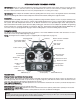
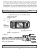
Charging jack - Port for charging the transmitter batteries with the included battery charger. On-off switch DATA INPUT lever - Used to change the values of the various functions displayed on the LCD screen. Liquid-crystal display screen (LCD) - Displays programming modes and values entered. MODE key - Used to scroll through and display the ten or eleven(PCM) different functions. SELECT key - Used to display the values for the current function.
• After the servos are installed, operate each servo over its full travel and check that the pushrods and servo arms do not bind or contact each other. Also make sure the controls do not require excess force to operate. If there is an objectionable buzzing sound coming from a servo, there is probably too much resistance in the control. Find and correct the problem. Even if there is no servo damage, excess battery drain will result.
RECEIVER AND SERVO CONNECTIONS Connect the servos to the receiver to perform the functions indicated: Receiver output channel Function 1 Aileron -or or-right flaperon -or or-right elevon (for tailless models) 2 Elevator -or or-left ruddervator (for V-tail models) -or or-left elevon (for tailless models) 3 Throttle 4 Rudder -or-right ruddervator (for V-tail models) 5 Retractable landing gear 6 Flap -or-left flaperon 7 Not used B/8 Receiver on/off switch (the plug colored red goes int o the r
called “memory.” If, for example, only two flights are made each time you go flying, the batteries will not have “reached” very far down into their full capacity. After doing this several times the batteries will “remember” and eventually “think” they can supply only enough power for two flights. After two flights the batteries may not provide enough power to operate the system, thus causing a crash.
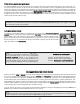
Model memory number and model name The Futaba T6EXAP stores model memories for six models. This means all the data (control throws, trims, end points, etc.) for up to six different models can be stored in the transmitter and activated at any time (depending upon which model you choose to fly that day).
Model Select/Data Reset / Modulation Select/Model Name MODL Model select function To select model memory: 1. Access the Model Select function in the programming mode (by pressing the MODE and SELECT keys simultaneously and holding them down for one second). The number for the current, active model will be blinking. 2. To activate a different model memory press the DATA INPUT lever until the desired model number appears. 3. Now the model has been selected.
2.Once the desired model number is displayed on the screen, press the SELECT key. A NAME will appear on the screen. 3. Choose a character for the first digit by using DATA INPUT lever. Then move to the next digit by pressing the SELECT key and choose a character in the same way. Continue choosing characters for the third and fourth digits. You can use up to four characters for the name.
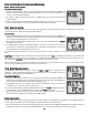
EXPO Exponential Settings The “exponentials” are in the same function as the dual rates. (Pressing the MODE key will take you to the next function which is End Point Adjustments). The same as dual rates, “expos” can be set for both switch positions. Negative exponential (-) decreases initial servo movement. Positive exponential (+) increases initial servo movement. The exponential “curve” may be set anywhere between -100% and +100%. To set the exponentials: 1. Enter the programming mode.
TRIM - Trim Settings There are four trim levers (“trims”) on the front of the transmitter. Three of the trims are for adjusting the neutral position of the aileron, elevator and rudder servos. The fourth trim is for setting the idle r.p.m. of the engine when the throttle stick is all the way down. The intended use of the trims is to make small servo adjustments, in flight, to get the model properly “trimmed” (so it will fly straight-and-level).
3. Push SELECT key to call the screen for selecting channels to control “ MAS ” (Master) mixing. Then select the channel by pushing DATA INPUT lever . Channel 1 (aileron) in this figure is assigned to the master. 4. Push SELECT key to call the screen for selecting channels to control “SLV” (Slave) mixing. Then select the channel by pushing DATA INPUT lever. Channel 4 (rudder) in this figure is assigned to the slave. 5. Press the SELECT key twice to display the flashing % sign.
3. Push the DATA INPUT lever upward. This will cause the flashing “INH” display to change to a flashing “ON” display. Now the mixing is on. 4. If needed to set ailerons differential. Press the SELECT key to display the flashing “%” sign.
V-TL V-tail mixing Intended for V-tail aircraft (such as a Beechcraft Bonanza), V -tail mixing allows the ruddervators to operate both as rudders and elevators. The same as the other mixes, V -tail mixing requires that each ruddervator be operated by a separate servo. To activate V-tail mixing: 1. Connect the left ruddervator servo to channel 2 (elevator) in the receiver and connect the right ruddervator servo to channel 4 (rudder) in the receiver.
ELVN Elevon mixing Intended for tailless, “flying wing” models such as delta wings and flying wings, elevon mixing mixes channel 1 (aileron) to channel 2 (elevator) allowing the elevons to operate in unison (as elevators) or in opposition (as ailerons). This function requires that each elevon be operated by a separate servo. *If necessary, use the Servo Reversing function to achieve the correct direction of servo throws. To activate elevon mixing: 1.
F/S Fail Safe (PCM mode only) The Fail Safe function is used to prescribe what the PCM receiver will do in the event radio interference is received, and doesn’t work FM(PPM) receivers. In this menu, you may select from one of two options of operation for each channel. The “NOR”(normal) setting holds the servo in its last commanded position, while the “F/S”(Fail Safe) function moves each servo to a predetermined position. Throttle channel is set to “F/S” as a default. All the other channels are set to “NOR”.
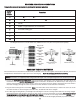
FLOW CHART 6EXAP FUNCTIONS Stick Mode (Screen at Startup) To enter or leave Programming Mode, press MODE and SELECT keys simultaneously for one second. To change the Stick Mode, turn on the transmitter holding MODE and SELECT keys down simultaneously. Use the DATA INPUT lever to display the desired stick mode.
OTHER 6EXAP FUNCTIONS Trainer switch To utilize the trainer function, the appropriate trainer cord (available separately) and a second Futaba transmitter (usually provided by your flight instructor or R/C club) will be required. When two radios are connected with the trainer cord, they are both capable of operating the model, but it's usually best for the instructor to hold the radio that has been setup for the plane to be flown (as it is already programmed to fly the model).
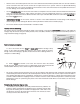
Adjustable-length control sticks The control stick length is adjustable to make the transmitter more comfortable to hold and operate. To adjust the length, hold the locking piece (B) and turn the stick tip (A) counterclockwise. Turn the locking piece B up or down to lengthen or shorten the stick. When the length is suitable, lock the stick in position by turning locking piece B counterclockwise. Changing the 6EXAP stick mode The transmitter may be operated in four different stick “modes” (1, 2, 3 & 4).
FLIGHT PREPARATION Flight preparation is to be done at the flying field. IMPORTANT: Your radio control system transmits a signal on a certain frequency. Be certain you know what the frequency is. This is expressed as a two-digit number (42, 56, etc.), and can be found on the container the transmitter came in and is also located on the transmitter and receiver. There are several different frequencies, but there is still a chance that someone else at the flying field may be on the same frequency as you.
MODEL DATA RECORDING SHEET (Make copies before using) Model name: Model No.
FUTABA ACCESSORIES AND REPLACEMENT PARTS (for USA) REPLACEMENT PARTS ANT-5 Transmitter antenna................................. FUTM5040 NR-4J 4.8 Volt, 600 mAh receiver battery .......... FUTM1280 NT-8F 600B 9.6 Volt, 600 mAh Transmitter battery .............................. FUTM1440 SWH-13 Switch Harness w/charge plug .............FUTM4370 FSH-6X Servo arm.............................................. FUTM2030 FSH-6S Servo arm..............................................