
Manual


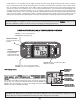

Aileron, Elevator & Rudder
dual rate switch
Antenna
Retractable landing
gear switch / CH.5
Flap control
dial / CH.6
Carrying handle
Liquid-crystal display
screen (LCD)
Throttle/rudder
control stick
MODE key
SELECT key
Trainer switch
Neck strap hook
Charging jack
On-off switch
Rudder trim
lever
Throttle trim
lever
DATA INPUT lever
Aileron trim lever
Elevator trim lever
Aileron/elevator
control stick
4
throttle cut
button
INTRODUCTION TO THE 6EXAP SYSTEM
INTRODUCTION TO THE 6EXAP SYSTEM
IMPORTANT!:
IMPORTANT!:
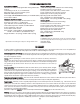
Always turn on the transmitter first, then the receiver. When turning off the system, always turn off the receiver
first. The object is never to have the receiver on by itself. Otherwise, the servos or control surfaces could be damaged, or in
the case of electric-powered models, the motor may unexpectedly turn on causing severe injury.
IMPORTANT!:
IMPORTANT!:
Never collapse the transmitter antenna by pushing down from the top. If one of the segments becomes momentarily
stuck you may damage the antenna. Instead, collapse the antenna from the bottom, drawing in one segment at a time.
Transmitter
Transmitter
Transmits in both FM (PPM) and PCM by selecting modulation/cycling transmitter. Requires receiver of proper modulation. The
liquid-crystal display (LCD) on the face of the compact, ergonomically-designed case is easy to read and allows rapid data input.
The system also holds independent memories for six different models. The new, adjustable-length control sticks provide an
improved feel. External switches operate dual rates (D/R), landing gear, and trainer cord or “buddy-box” capabilities. Programming
features include servo reversing and E.P.A on all channels, dual rates, exponentials and programmable mixing. Additionally, any
one of four, factory-set, preprogrammed
“wing-type” mixers including flaperon, V-tail, elevon mixing may be selected.
Transmitter controls
Transmitter controls
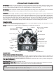
The diagram and explanations briefly describe the functions of the Futaba T6EXAP transmitter. Full instructions on how to
operate the controls are provided beginning on page 9.
NOTE:
NOTE:
The diagram shows a Mode 2 system as supplied. (More on flight modes on page 21).
DESCRIPTIONS:
DESCRIPTIONS:
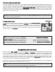
Aileron, Elevator and Rudder dual rate switch
Aileron, Elevator and Rudder dual rate switch
Use this switch to “flip” between two aileron, elevator and rudder control throw settings. The throws can be set up however you
prefer, but generally, when the switch is “up” the throws are greater (“high rate”) and when the switch is “down” the throws are less
(“low rate”). This switch also flips between exponential rates (if used).
Flap control dial/Channel 6 -
Flap control dial/Channel 6 -
This dial operates the servo connected to channel 6 in the receiver if your model has flaps this is
the control used to operate them.
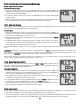
Neck strap hook -
Neck strap hook -
Mounting point for optional neck strap.
Aileron/elevator control stick -
Aileron/elevator control stick -
Operates the servos connected to channel 1 (aileron) and channel 2 (elevator) in the receiver.
Trim levers (all) -
Trim levers (all) -
Used to shift the neutral or center position of each servo as labeled in the diagram.
NOTE:
NOTE:
The throttle trim lever is intended for fine tuning the throttle servo when the engine is at idle. Throttle trim does
not affect the throttle servo when the throttle control stick is all the way up (so idle r.p.m. can be adjusted without
affecting throttle settings through the rest of the stick movement).