INSTRUCTION MANUAL 1M23N26602
8J-2.4GHz 8-CHANNEL RADIO CONTROL SYSTEM INSTRUCTION MANUAL Technical updates and additional programming examples available at: http://www.futaba-rc.
TABLE OF CONTENTS Trim....................................................................45 Sub Trim ............................................................46 Servo ..................................................................47 Fail Safe .............................................................48 Flaperon (ACRO Only) .....................................49 Flap Trim (ACRO Only) ....................................51 AIL DIFF (ACRO Only) ...................................
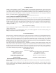
INTRODUCTION Thank you for purchasing a Futaba® S-FHSS-2.4GHz* 8J series digital proportional R/C system. This system is extremely versatile and may be used by beginners and pros alike. In order for you to make the best use of system, please consult the manual, our online Frequently Asked Questions (on the web pages referenced below), your hobby dealer, or the Futaba Service Center.
1. This product may be used for model airplane or surface (boat, car, robot) use. It is not intended for use in any application other than the control of models for hobby and recreational purposes. The product is subject to regulations of the Ministry of Radio/Telecommunications and is restricted under Japanese law to such purposes. 2.
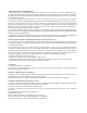
Meaning of Special Markings Pay special attention to safety where indicated by the following marks: DANGER - Procedures which may lead to dangerous conditions and cause death/serious injury if not carried out properly. WARNING - Procedures which may lead to a dangerous condition or cause death or serious injury ! ! % physical damage is high.
$ as well as the presence and location ! ~ power lines, tall buildings, or communication facilities as there may be radio interference in their vicinity. ! ! * * ' * mile range, or you may lose control of your aircraft or cause someone else to lose control.
A QUICK INTRODUCTION TO THE 8J SYSTEM Note that in the text of this manual, beginning at this point, any time we are using a feature’s specialized name or abbreviation as seen on the screen of the 8J, that name, feature, or abbreviation will be exactly as seen on the radio’s screen, including capitalization and shown in a DIFFERENT TYPE STYLE for clarity. Any SWITCH A, VR, or the THROTTLE STICK, those words will be displayed as they are here.
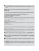
RECEIVER: R2008SB `||[;~ ; ~]; ! used with conventional system servos, etc. in addition to S.BUS system compatible servos and gyros, etc. Link switch LED (Connectors) Channel 1 output Channel 7 output for conventional system S.BUS Port R2008SB Channel 8 output for conventional system /Battery terminal Antenna ' ;Y ;; ;; ;; K 4CH.
The following additional accessories are available from your dealer. Refer to a Futaba catalog for more information: { ||~/FT2F2100B Transmitter battery pack - the transmitter battery pack may be easily exchanged Y ! ! ! the instructor on a separate transmitter.
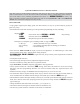
TRANSMITTER CONTROLS - AIRPLANE Built-in Antenna Carrying Handle VR Flap Trim Control Digital Trim 5 /CH7 Control This controls CH6, and if flaperon mixing is activated controls the flap.
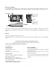
TRANSMITTER CONTROLS - HELI Built-in Antenna Carrying Handle VR CH8 Knob Digital Trim 5 SW(C) Governor Switch/CH7 SW(B) Rudder Dual Rate Switch SW(A) Elevator Dual Rate Switch SW(F) Idle-up 3 Switch /Gyro/CH5 SW(D) Aileron Dual Rate Switch SW(H) Trainer Switch SW(E) SW(G) Throttle - Hold Switch Idle-up 1&2 Switch Digital Trim 6 Throttle/Collective Pitch & Rudder Stick Elevator /Aileron Stick Power LED Throttle/Collective Pitch Trim Lever Elevator Trim Lever Aileron Trim Lever Rudder Trim Lever
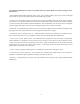
INSTALLATION AND REMOVAL OF THE TRANSMITTER BATTERY The T8J transmitter is designed to work with either four (4) AA alkaline dry cell batteries, or HT5F1700B/ FT2F2100B battery pack, both available separately. The transmitter batteries used are a matter of personal preference. AA Alkaline batteries are available at any local hobby shop, grocery store, etc. A battery pack will need to be purchased from a hobby shop.
SWITCH ASSIGNMENT TABLE ! [ $ ` below. $ [ ! Y Z ~ {Y[ Z % ! AUX-CH.
RECEIVER AND SERVO CONNECTIONS (Wing Type) Receiver Output and Channel 1 2 3 4 5 6 7 8 ACRO (FLAPERON) Aircraft (ACRO) ailerons/aileron-11 ! Y` Y2 elevator throttle rudder spare/landing gear/aileron-21,3 ! Y ^ _ ! Y Y`2 spare/aileron-21 spare/elevator-24/mixture control AIL22 FLP12 (CH6) AIL12 FLP22 (CH1) ACRO (FLAP) Y`2,3 AIL21 (CH7) AIL (CH1) AIL11 (CH1) FLP (CH6) 1 Aileron Differential mode (AILE-DIFF). Flaperon mode.
CHARGING THE BATTERIES (When the rechargeable battery option is used) Charging Your System’s Batteries 1. Connect the transmitter charging jack and batteries to the transmitter and receiver connectors of the charger. 2. Plug the charger into a wall socket. 3. Check that the charger LED lights.
ADJUSTING THE IENGTH OF THE CONTROL STICKS Stick tip A Locking piece B \ Z Z transmitter more comfortable to hold and operate. To lengthen or Z Z Z ! locking piece B and turning stick tip A counterclockwise. Next, move the locking piece B up or down (to lengthen or shorten). When the length feels comfortable, lock the position by turning locking piece B counterclockwise.
RANGE CHECK THE RADIO Z ! ! Z ! ^! ! Z ! _ Z ! adequate operational range. We have installed a special “Power Down Mode” in the T8J in order to perform an operational ground range check.
RADIO INSTALLATION Follow these guidelines to properly mount the servos, receiver and battery. $ Z alignment tab on the battery, switch and servo connectors is oriented correctly and “keys” into the corresponding notch in the receiver or connectors before plugging them in. When unplugging connectors, never pull on the wires. Always pull on the plastic connector instead.
! ! Z ! vibration during flight, provide a slight amount of slack or extra so that the wire sticks out slightly and fasten it at suitable points. In addition, periodically check the wire during daily maintenance. Margin in the lead wire. Fasten about 5-10cm from the servo outlet so that the lead wire is neat. IMPORTANT: Since the 2.
Antenna Antenna *The two antennas should be placed at 90 degrees to each other. *The main purpose of the photo demonstrates how the antenna should be placed. ! " & ~ vibration, shock, and temperature extremes. For protection, wrap the receiver in foam rubber or other vibration-absorbing materials.
LINK PROCEDURE (T8J transmitter/R2008SB): Each transmitter has an individually assigned, unique ID code. In order to start operation, the receiver must be linked with the ID code of the transmitter with which it is being paired. Once the link is made, the ID code is stored in the receiver and no further linking is necessary unless the receiver is to be used with another transmitter. When you purchase additional R2008SB receivers, this procedure is necessary; otherwise the receiver will not work. 1.
S.BUS INSTALLATION This set uses the S.BUS system. The wiring is as simplified and clean mounting as possible, even with models that use a large number of servos. In addition, the wings can be quickly installed to the fuselage without any erroneous wiring by the use of only one simple wire, even when there are a large number of servos used.
TRANSMITTER DISPLAYS & BUTTONS " ! ! ! ~ ! ! ¡ ! reversed, and travels and trims will be wrong, potentially leading to a crash.
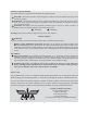
WARNING & ERROR DISPLAYS An alarm or error indication may appear on the display of your transmitter for a number of reasons, including when the transmitter power switch is turned on, when the battery voltage is low, and several others. Each display has a unique sound associated with it, as described below. LOW BATTERY ERROR: Warning sound: Continuous beep until transmitter is powered off. The LOW BATTERY warning is displayed when the transmitter battery voltage drops below 4.1V. (5CELL mode 4.
AIRCRAFT (ACRO) MENU FUNCTIONS Model Select .....................................................27 Model Copy ......................................................27 Model Data Reset...............................................28 Model Name ......................................................29 Parameter ...........................................................30 Model Type ........................................................30 RX select (S-FHSS /FHSS) ...............................31 ATL .....
MAP OF ACRO FUNCTIONS (Startup screen) To return to the Startup screen, press the End key. (Menu 1/3) To enter the Menu, press the + key for one second. ( for one second) (Menu 2/3) or ACRO Menu (Menu 3/3) or Press 㸩㸫Key to page up and down through the 3 pages of screens in each menu. Note that all functions which have more than one page have a <1/3> indicator in the upper right hand corner to indicate page 1 of 3 or page 2 of 3 / 3 of 3. Use Jog Key to highlight function in Menu screen.
A LOOK AT THE RADIO'S FUNCTIONS STEP BY STEP MODEL SELECT submenu: includes three functions that manage model memory: MODEL SELECT, MODEL COPY and MODEL RESET. Since these functions are all related, and are all basic features used with most models, they are together in the MODEL SELECT submenu. MODEL SELECT: This function selects which of the 20 model memories in the § are indicated after its number.
GOAL of EXAMPLE: Copy model 3 into model 5. STEPS: INPUTS: Open the menu, then open MODEL for 1 second. SELECT submenu. if required to MODEL SELECT. NOTE: This is one of several functions for which the radio requires Confirm you are currently using the If SELECT does not indicate 3, use MODEL proper model memory. (Ex: 3) SELECT, p. 27. Go to MODEL COPY and choose the to COPY. to 5. model to copy into. (Ex: 5) K for 1 second. Sure? displays. * Close.
MODEL NAME/USER NAME: MODEL NAME assigns a name to the current model memory. By giving each model a name that is immediately recognizable, Z ' a crash.
Z ! PARAMETER submenu: Z & " § " ¯S-FHSS or FHSS]? # trim on channel 3 (ATL)? (ACRO) using the MODEL RESET: see p. 28.
Receiver modulation select (RX): sets the type of modulation transmitted. The modulation of your receiver will determine whether you utilize S-FHSS or FHSS setting in RX during transmission. ! Z ! ! ~ ; ^F/S ) settings as you intended (see p. 48).
Adjustable travel limit (ATL_& Z # TRIM LEVER (THROTTLE TRIM) effective only at low throttle, disabling the trim at high throttle. This prevents pushrod jamming due to idling trim changes. This function defaults to ON. If you are not using channel 3 for throttle, you may want trim operation the same as on all other channels. To do so, set ATL to OFF. If you need the ATL ! Z ! THR-REV setting.
Home screen display mode selection (HOME-DSP): selects the display item in the home screen. USER NAME mode USER NAME: displays USER NAME in the home screen. (default) The default USER NAME ! « ! « & ` DT5/DT6: displays the current DT5 and DT6 position in the home screen. THR/PIT: displays the current throttle and pitch position in the home screen.
GOAL of EXAMPLE: STEPS: INPUTS: Change BATT TYPE from 4CELL to 5CELL. Open the menu, then open PARAMETER for 1 second. submenu. to PARAMETER. Go to BATT TYPE and change setting. (Ex: 5CELL) to BATT TYPE. to 5CELL. Close. Model data transmission (MDL-TRANS): Transmission of model data is possible with T8J transmitters. Data transfer is performed on radio. The present model is MDL-TRANS with each transmitter. As for a receiving side, the present model data is rewritten.
MDL-TRANS [ T8J of the transmits side ] 1. The data of a model to send is called by MDL-SEL. 2. MODE of MDL-TRANS is set to TRANSFER . 3. Execute . [ T8J of the receives side ] *It receives for 10 seconds. 1. The clear model is called by MDL-SEL. 2. MODE of MDL-TRANS is set to RECEIVE . 3. Execute . Servo reversing (REVERSE): changes the direction an individual servo responds to a CONTROL STICK motion. KK$ ! SWASH AFR (p. 75) before reversing any servos.
End Point of servo travel adjustment ( END POINT ): the most flexible version of travel adjustment available. It % ! directions. Again, for CCPM helicopters, be sure to see SWASH AFR (see p. 75) prior to adjusting end points.
Engine idle management: IDLE-DOWN and THR-CUT& Z THROTTLE TRIM to provide a simple, consistent means of engine operation. No more fussing with getting trim in just the right spot for landings or Z ¡ % THROTTLE-NEEDLE (p. 62) and THROTTLE DELAY (p. 63).
Throttle cut (THR-CUT): provides an easy way to stop the engine by flipping a switch (with THROTTLE STICK at _ Z HELI, there is an additional setting, THR-HOLD. See p. 78. § ! NULL to avoid accidentally assigning it to a switch, which might result in an unintentional dead Z & IDLE-DOWN and THR-CUT on p. 37.
Dual/triple rates and exponential (D/R,EXP): assigns adjusted rates and exponential. Dual/Triple Rates: ! rates affect the control listed, such as aileron, not just a single (ex: channel 1) % ! when using FLAPERON or AIL-DIF ! when using AILEVATOR or ELEVON or a CCPM helicopter.
GOAL of EXAMPLE: STEPS: Set up dual rates and exponential in a Open D/R,EXP. HELI model. INPUTS: for 1 second. to D/R,EXP. Choose channel. to desired channel. K to No. Set rate and exponential (Ex: high rate ± {³ |³ _ to D/R. Go to 2nd switch position and set rate and exponential.
GOAL of EXAMPLE: STEPS: Set up aileron triple rates on SWITCH Open D/R,EXP function. C {³ ^ _ `{³ ^ _ |³ ^ aerobatics) and exponential settings of Choose the channel to change |³ µ{³ Y|³ (Ex: aileron is already selected) ACRO model. $ INPUTS: for 1 second.
TIMER submenu ^ _& Z Z ! Z Z Z ! TIMER<1> TIMER<2> ^ _ Adjustability: K & below 0.
Auxiliary channel function (AUX-CH_& ! {Y[ Adjustability: K {Y[ ! SWITCH (A-H), TRIM LEVER (DT5 and DT6), or KNOB [VR]. $ ! Z ! K «]« ! ^ & ' ` channels for 2 rudder servos.
TRAINER: for training novice pilots with optional trainer cord connecting 2 transmitters. The instructor has several levels of controllability. Adjustability: NOR: When the TRAINER SWITCH is ON, the channel set to this mode can be controlled by the student.
TRIM submenu: resets and adjust effectiveness of digital trims. The 8J has digital trims which are different from conventional mechanical trim sliders. Each TRIM LEVER Y TRIM LEVER is pressed, the trim is changed a selected amount. When you hold the TRIM LEVER, the trim speed increases. The current trim position is graphically displayed on the start up screen. The TRIM submenu includes two functions that are used to manage the trim options.
SUB-TRIM& Z Y`| µ`| | the default being no SUB-TRIM. " ! Z SUB-TRIM Z SUB-TRIM values as small as possible. Larger SUB-TRIM § restricted on one side.
SERVO display and cycle submenu: § Y[ The servo submenu includes two features: Real-time bar-graph display to demonstrate exactly what commands the transmitter is sending to the servos.
FailSafe (loss of clean signal and low receiver battery) submenu (F/S): sets responses in case of loss of signal or low Rx battery. FailSafe (F/S): instructs a 2.4G receiver what to do in the event radio interference is received. Adjustability: ! ^FHSS mode: ch2 only) NOR (normal) setting holds the servo in its last commanded position.
]K ;& Aircraft wing types (ACRO): There are 3 basic wing types in aircraft models: ; $ ^ \Y _ This is the default setup and requires no specialized wing programming. ; $ ` ; ; Y ^ _ $ ` Z ! ; ELEVON.
Using FLAPERON (ACRO): The FLAPERON mixing function uses one servo on each of the two ailerons, ! raise/lower simultaneously. Of course, aileron function (moving in opposite directions) is also performed. Once FLAPERON K « « ^ ELEVATOR-FLAP mixing), the radio commands both ! % ! FLAPERON.
Using FLAP-TRIM (ACRO) FLAP-TRIM ¯VR¹ ^ & FLAP-TRIM is made active with AILDIFF, it will not have any effect. The ONLY function that allows control of the AIL-DIFF AIRBRAKE.) Most modelers use ! AIRBRAKE movement of a switch.
Using Aileron Differential (AILE-DIFF)(ACRO): # Y ^ _ ! ^ _ K AILE-DIFF controlling proper aileron ` K K ! Z AILE-DIFF, except if using AIRBRAKE (Note Z FLAP-TRIM active while using AILE-DIFF, it will not have any effect.
Aircraft tail types (ACRO): There are 4 basic tail types in aircraft models: ; $ ^ \Y _ $ ` AILVATOR p. 54. Y $ ` ELEVON. p. 53. V-TAIL. Model uses 2 surfaces, at an angle, together to create yaw and pitch control. see V-TAIL. p. 55.
Dual Elevator Servos (with a rudder) (AILEVATOR) (ACRO): Many models use two elevator servos, plugged in separate ^ ELEVON Y V-TAIL, p. 55.) 7 $ ! % § travel. ! ` surfaces.
Using V-TAIL (ACRO): V-TAIL Y ! functions are combined for the two tail surfaces. Both elevator and rudder travel can be adjusted independently on each surface. NOTE: If V-TAIL is active, you cannot activate ELEVON or AILEVATOR functions. If one of these functions is active, an error message will be displayed and you must deactivate the last function prior to activating V-TAIL.
!SNAP-ROLL) (ACRO): ! the same input every time. It also removes the need to change dual rates on the 3 channels prior to performing a snap, as SNAP-ROLL Z the same position, regardless of dual rates, inputs held during the snap, etc.
GOAL of EXAMPLE: STEPS: INPUTS: Activate SNAP-ROLL. Adjust aileron to Open the SNAP-ROLL function. for 1 second. 105% ,elevator travel to 95% , rudder to SNAP-ROLL. travel to 120% in the right/up snap. to MIX. to OFF or ON. Activate SAFE-MODE so snaps cannot be Activate the function. performed when gear is down. Adjust the travels as needed. (Ex: to AIL. to 105%. aileron to 105%, elevator to 95%, rudder to ELE. to 95%. Adjust rudder travel in the left/down to 120%.) snap to 105%. to RUD. to 120%. E or G up.
MIXES: 4 4 & Mixes are special programs within the radio that command one or more channels to act together with input from only one Z Z ! There are a variety of types of mixes.
ELEV-FLAP mixing (ACRO): § Z ELEV-FLAP Y ELEVATOR STICK is moved. It is most Z ^ _ Adjustability: Rate& Y||³ ^ _ µ|| ^ _ µ{|³ ^ Y when the ELEVATOR STICK is pulled to provide full up elevator.
AIRBRAKE mixing (ACRO): AIL1 FLP ELE AIL2 Z FLAPERON and AILEVATOR, AIRBRAKE Y done for you within the radio. AIRBRAKE ^ _ ^ _ ^ _ ^ _ Z together.
GOAL of EXAMPLE: STEPS: Activate AIRBRAKE on a FLAPERON . K FLAPERON is active. model. Adjust the flaperon travel to Open the AIRBRAKE function. 75%,with negative elevator (push) of 25%. Activate the function. INPUTS: see FLAPERON instructions. for 1 second. to AIRBRAKE. Switch C in up position. to MIX. to OFF. SW selection. A position is turned ON by down with a center. to SW. to SWC. Adjust the travels as needed. (Ex:Ailerons each 75%, Elevator -25%.) to AIL1. to 75%. to ELEV. to -25%.
THROTTLE-NEEDLE mixing (ACRO/HELI): (ACRO) (HELI) Y ^K[_ THROTTLE-NEEDLE Y THROTTLE STICK inputs for perfect engine tuning at all throttle settings.
Where next? Set up THROTTLE DELAY % & # Adjust throttle and Ch8 END POINTs: see p. 36. Set up programmable mixes, for example, AILERON-to-RUDDER: see p. 65. ! Y º º Throttle delay function THR-DELAY (ACRO): The THR-DELAY function is used to slow the response of the throttle servo to simulate the slow response of a turbine engine.
Throttle curve (THR-CURVE)(ACRO): This function adjusts the throttle operation curve for optimum engine response Z NOTE: If the throttle EXP function is activated, you cannot use THR-CURVE function simultaneously. Adjustability: ; ! GOAL of EXAMPLE: STEPS: Adjust throttle curve until engine idles Open the THR-CURVE function. reliably. Activate the function. % Y{ position. INPUTS: for 1 second. to THR-CURVE.
LINEAR PROGRAMMABLE MIXES (PROG.MIX1-4): Your 8J contains four separate linear programmable mixes. (Note that P.Mixing { {Y ; K] $ ¼ ; _ There are a variety of reasons you might want to use these mixes.
On/off choices: SWITCH: Any of the positions of any of the 8 switches may be used to activate a mix. UP&CT, CT&DN options allow the mix to be ON ` # #Y SWITCH. NULL: No SWITCH can turn this mix OFF. This mix is active at all times. THR: Turned on/off by THROTTLE STICK movement. Trigger point/direction are selectable. Ex: OFSY Y^ _ mix to open gear doors at idle, which is only active if throttle is below half.
GOAL of EXAMPLE: Set up a FLAP-ELEV mix: STEPS: INPUTS: Open an unused programmable mix. for 1 second. (Ex: use P.MIX3 Y to P.MIX1-6. ON when SWITCH C is in the down for FLAP-ELEVATOR.) to 3 position. up (spoilers), {³ move down, Activate the function. to MIX. to ON. Choose master and slave channels. already FLP (Ex: no need to change MASTER/SLAVE.) already ELE $ C OFS, DT5, DT6 or to MASTER .
CURVE PROGRAMMABLE MIXES (PROG.MIX5-6): \ [ ACRO/HELI programs contain two separate curve programmable mixes. There are a variety of reasons you might ¨ Y curve mix is the THROTTLE-NEEDLE % ! { % at 5 points along its RPM range.
GOAL of EXAMPLE: STEPS: INPUTS: Set up a RUDD-ELEV curve mix on a Open an unused curve programmable for 1 second. model that pitches down severely at mix. (Ex: use PROG.MIX6 since it is to P.MIX1-6. full rudder and not at all with minimal Y RUDDER-ELEV.) to 6. rudder input, and pitches worse on right rudder than left: Activate the function. to MIX. P-1: 25% P-2: 8% P-3: 0% P-4: 10% P-5: 28% ON when SWITCH C is down.
GYA gyro mixing XYF $ \ K; Z \ #{|& \ #{& FLAPERON.
_ ` { | Z Gyros: Z Y ! ! Z Y information on gyro types, please see p. 70.
HELICOPTER (HELI) MODEL FUNCTIONS K ]K ;.......................................... 72 Table of contents and reference info for helicopters . 72 Model Select .....................................................27 Model Copy ......................................................27 Model Data Reset...............................................28 Model Name ......................................................29 Parameter ...........................................................
HELI-SPECIFIC MENU FUNCTIONS MODEL TYPE: This function of the PARAMETER submenu is used to select the type of model programming to be used. Before MODEL TYPE ! is an 8JA, the default is ACRO [ HELI(H-1).
GOAL of EXAMPLE: STEPS: INPUTS: Change the MODEL TYPE and SWASH Confirm you are currently using the Z # on top left. TYPE of model #3 from aircraft to 120 proper model memory. (example: 3) KK$ ` Z If it is not the correct model (example:3), unison for collective pitch and aileron see MODEL SELECT. [HELI(HR3)]. Open PARAMETER submenu. for 1 second. to PARAMETER. Select proper TYPE. (HELICOPTER) & ' to TYPE. to HELICOPTER. for 1 second.
SWASH AFR (not in SWH1): Swashplate function rate settings (SWASH AFR) reduce/increase/reverse the rate (travel) of the aileron, elevator (except H-2 ) and collective pitch functions, adjusting or reversing the motion of all servos involved in that function, only when using that function. Since these types utilize multiple servos together to % § REVERSE or END POINT would not properly correct the travel of any one control.
Swash Mixing (SWH MIX): This function can be set for each flight condition, and is used to correct the tendency of the model to change when the rotor is tilted by aileron, elevator, and rudder controls. Adjustability: $ ! Y|| ||³ GOAL of EXAMPLE: STEPS: When the right roll is carried out, an Open SWH MIX function. elevator is down and an adjustment is needed. Activate the function. INPUTS: for 1 second. to SWH MIX. to 2/2 page to ON.
Throttle Mixing (THROTTLE MIX): This function can be set for each flight condition, and is used to correct the tendency of the model to change altitude when the rotor is tilted by aileron, elevator, and rudder controls. Adjustability: $ ! | ||³ GOAL of EXAMPLE: STEPS: Correct the tendency of the model to Open THROTTLE MIX function. change altitude. INPUTS: for 1 second. to THROTTLE MIX. Activate the function. to MIX Adjust the rate.
Setting up the Normal Flight Condition: ' collective pitch curves are adjusted to provide consistent engine RPM despite the increase/decrease in collective pitch of ! Z ! ^ Z { _ $ ^ Z _ Z As the 2 curves and revo.
GOAL of EXAMPLE: STEPS: Set up Normal Flight Condition Open the THR-CURV/NOR function. Throttle/Collective Pitch Curves and % ^ & 5%.) Revo. Base point: Adjust base point of throttle curve until engine idles reliably on the Open the PIT-CURV/NOR function. ground. Adjust base point of collective % ^ & 8%.) Y blade pitch. Apply throttle until the Open the REVO. /NORM function.
THR-HOLD: This function holds the engine in the idling position and disengages it from the THROTTLE STICK when SWITCH E ^[_ ^[ _ Y Prior to setting up THR-HOLD Z Z ! is opened fully at high throttle. Then, use the digital trim to adjust the engine idle position.
THR-CURVE and PIT-CURVE& {Y ' ! ! $ K % ! Y Y ` Y # a separate collective pitch curve is available for throttle hold.
K Z & ¾Y`| "¾ µ`|³ K Z & ¾µ`| "¾ Y`|³ % Z ! Y Y ^ Z !
OFFSET: Optional separate trims in addition to those for the normal condition. This function is used to automatically change Z Y helicopter tends to drift to the right at high speeds, so an aileron offset may be applied to offset the helicopter to the left.
DELAY: The Delay function provides a smooth transition between the trim positions whenever OFFSET, REVO. MIXING, or THROTTLE HOLD functions are turned on and off. Adjustability: ; ! pitch. " {|³ Z ! Y new position...quite a long time.
HOVERING ADJUSTMENTS (HOV-THR and HOV-PIT): Y % Y Z curves for ideal setup.
HIGH/LOW PITCH (HI/LO-PIT): ! % § Y ` Y # _ ^ Y Adjustability: \ Z ! ^ { _ CONDITION SELECT function (p.78).
01 2 023 "2 7 $ ' " ! ^ _
Z ` # ! ! CH. Gain Example for AVCS/Heading-hold Gyros (GY) GY 100% NOR 0% 100% AVC "Normal Mode" 0% "Heading Hold Mode" 50% +100% STD GOAL of EXAMPLE: STEPS: INPUTS: ; Y K; Open and activate the GYRO SENSE for 1 second. Y K; Y function.
GOVERNORS: GV-1 connections Magnetic sensor Throttle servo Control amp Mixture servo Connected only when fuel mixture function used.
! ; ; ! ; Expert Tip: Mounting the governor to the counter gear instead of the fan ! § BPS-1 RPM Sensor which attaches a sensor to an exclusive engine directly is simpler.
TX SETTING " Z " % % # \ ] % ' " + − ․ 1.
④ Z and left (up and down). is displayed beside ^] DOWN). | is pushed. ⑤■ ⑥ It is the display of "Complete" and is END.