
User's Manual


p.4FUTABA
Ni04-009-1 rev5.0
2. POWER
2-1. Before turning on the power
Be sure to read this instruction manual prior to turning on the power of the modems.
Improper operations of the FDK modem may not only cause failures of communication but also cause
malfunctions and/or damages of this modem and the external equipment connected to this modem.
In order to establish proper communication between this modem and mobile stations, communication
parameters should be set by switches, which should be set before turning on the power switch.
In addition, since F utaba has specially defined the pin- ass ignment of interface c onnector for
RS-232C/RS-422/RS-485; please carefully confirm the wire identifications of the interface cable and pin layout.
2-2. Voltage of the power source
The input voltage to this modem should be within the range of 20Vdc and 29Vdc. Otherwise, this modem and
the external equipment connected to this modem may cause damages or malfunctions.
2-3. Connector for the power source
The type of the connector used for this modem is S2P-VH made by J.S.T. Mfg Co., Ltd. Supply the voltage
anywhere between 20Vdc and 29Vdc to the "+" marked terminal and connect the ground wire to the "-"marked
terminal.
Connector for the power source
Picture 2-3
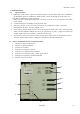
2-4. Power switch
The label "POWER" is printed beside the power switch of this modem. See picture 2-4
()
Pushing this switch toward "ON" will turn on the power switch and the LED indicator of the power on top of
the unit turns on green. O n t he other hand pushing the switch toward "OFF" will turn off the power. The
picture 2-4 shows "OFF" state.
Power switch
Picture 2-4