9CAP / 9CAF / 9CHP / 9CHF 9 CHANNEL RADIO CONTROL SYSTEM INSTRUCTION MANUAL Technical updates and additional programming examples available at: http://www.futaba-rc.com/faq/faq-9c.html Entire Contents © Copyright 2002 FUTZ8585 V1.
TABLE OF CONTENTS Other Equipment . . . . . . . . . . . . . . . . . . . . . . . . . . . . .64 GLIDER (GLID1FLP/2FLP) FUNCTIONS . . . . . . . . . . .65 Table of contents . . . . . . . . . . . . . . . . . . . . . . . . . . .65 Getting Started with a Basic 4-CH Glider . . . . . . . . .66 GLIDER-SPECIFIC BASIC MENU FUNCTIONS . .68 Model type (PARAMETERS submenu) . . . . . . . . . .68 GLIDER-SPECIFIC ADVANCE MENU FUNCTIONS 69 BUTTERFLY . . . . . . . . . . . . . . . . . . . . . . . . . . . . . .
INTRODUCTION Thank you for purchasing a Futaba® 9C series digital proportional R/C system. This system is extremely versatile and may be used by beginners and pros alike. In order for you to make the best use of your system and to fly safely, please read this manual carefully. If you have any difficulties while using your system, please consult the manual, our online Frequently Asked Questions (on the web pages referenced below), your hobby dealer, or the Futaba Service Center.
Application, Export, and Modification 1. This product may be used for model airplane or surface (boat, car, robot) use, if on the correct frequency. It is not intended for use in any application other than the control of models for hobby and recreational purposes. The product is subject to regulations of the Ministry of Radio/Telecommunications and is restricted under Japanese law to such purposes. 2.
Meaning of Special Markings Pay special attention to safety where indicated by the following marks: DANGER - Procedures which may lead to dangerous conditions and cause death/serious injury if not carried out properly. WARNING - Procedures which may lead to a dangerous condition or cause death or serious injury to the user if not carried out properly, or procedures where the probability of superficial injury or physical damage is high.
Always pay particular attention to the flying field’s rules, as well as the presence and location of spectators, the wind direction, and any obstacles on the field. Be very careful flying in areas near power lines, tall buildings, or communication facilities as there may be radio interference in their vicinity. If you must fly away from a club field, be sure there are no other modelers flying within a three-to-five-mile range, or you may lose control of your aircraft or cause someone else to lose control.
A QUICK INTRODUCTION TO THE 9C SYSTEM Note that in the text of this manual, beginning at this point, any time we are using a feature’s specialized name or abbreviation as seen on the screen of the 9C, that name, feature, or abbreviation will be exactly as seen on the radio’s screen, including capitalization and shown in a DIFFERENT TYPE STYLE for clarity.
MODULE: 72TP-FM • Module may be easily removed and a module on a different channel (or even band) reinserted to change the frequency on which the 9C transmits. • Module transmits both FM (PPM) and PCM. No need for a second module. • All transmission circuitry is included in the module, so no retuning is needed when changing channels or even bands. • Frequency band is changed by inserting a module on the proper band, including for international or ground model use.
CONTENTS AND TECHNICAL SPECIFICATIONS (Specifications and ratings are subject to change without notice.
The following additional accessories are available from your dealer. Refer to a Futaba catalog for more information: • CAMPac Memory module - the optional DP-16K CAMPac increases your model storage capability (to 14 models from 8) and allows you to transfer programs to another 9C transmitter. Note that data cannot be transferred to/from any other model of transmitter (i.e. 8U, 9Z, etc).
TRANSMITTER CONTROLS – AIRPLANE Antenna Be careful not to bend your antenna when you collapse or extend it. Dust Cap (optional CAMPac module plugs in here) VR(A) Flap Trim Control Antenna must be fully extended when flying. VR(B) CH8 Knob Carrying Handle This controls CH6, and if flaperon mixing is activated controls the flap. VR(C) Spoiler/CH7 Control SW(B) Rudder Dual Rate Switch This knob is disabled if aileron differential is activated.
TRANSMITTER CONTROLS – HELI Antenna Be careful not to bend your antenna when you collapse or extend it. Dust Cap (optional CAMPac module plugs in here) VR(A) Hovering - Pitch Knob Antenna must be fully extended when flying.
To remove, press the tabs together and gently pull rearwards. To install, line up the connector pins with the socket in the rear of the module and gently snap into position. RF module Trainer function /DSC function connector Ni-Cd battery pack Charging jack Battery connector location PUSH Battery cover NOTE: If you need to remove or replace the transmitter battery, do not pull on its wires to remove it. Instead, gently pull on the connector's plastic housing where it plugs into the transmitter.
RECEIVER AND SERVO CONNECTIONS Receiver Output and Channel 1 2 3 4 5 6 7 8 9 ACRO) Aircraft (A HELI) Helicopter (H GLID1FLP/GLID2FLP) Glider (G ailerons/right aileron1/combined right flap & aileron1 elevator throttle rudder spare/landing gear/left aileron1,3/combined left flap and aileron2,3 right flap (GLD2FLP) spare/ flap(s)/combined left flap and aileron2 spare/left aileron1 spare/second elevator servo4/mixture control spare aileron (cyclic roll) elevator (cyclic pitch) throttle rudder spare/gyro pit
Adjusting the length of the non-slip control sticks Stick tip A Locking piece B You may change the length of the control sticks to make your transmitter more comfortable to hold and operate. To lengthen or shorten your transmitter’s sticks, first unlock the stick tip by holding locking piece B and turning stick tip A counterclockwise. Next, move the locking piece B up or down (to lengthen or shorten). When the length feels comfortable, lock the position by turning locking piece B counterclockwise.
RADIO INSTALLATION While you are installing the battery, receiver, switch harness and servos into your model’s fuselage, please pay attention to the following guidelines: Wood screw Rubber grommet Brass eyelet Use the supplied rubber grommets when you mount each servo. Be sure not to over-tighten the screws. If any portion of the servo case directly contacts the fuselage or the servo rails, the rubber grommets will not dampen the vibration, which can cause mechanical wear and servo failure.
Range Testing Your R/C System Please note that different systems demonstrate different range checks and the same system will range check differently in different conditions. Also, the receiver antenna's installation affects the range test -- exiting the top of the model is ideal. This is a brief explanation of range test. For more in-depth specifics on receiver antenna mounting, additional checks if unsatisfactory rage is demonstrated, range checking with gasoline powered engines, etc, please see our F.A.Q.
The following frequencies and channel numbers may be used for flying aircraft in the United States: TRANSMITTER DISPLAYS & BUTTONS When you first turn on your transmitter, a confirmation double beep sounds, and the screen shown below appears.
WARNING & ERROR DISPLAYS An alarm or error indication may appear on the display of your transmitter for several reasons, including when the transmitter power switch is turned on, when the battery voltage is low, and several others. Each display has a unique sound associated with it, as described below.
AIRCRAFT (ACRO) MENU FUNCTIONS Please note that all BASIC menu functions are the same for airplanes (ACRO), sailplanes (GLID1FLP/2FLP), and helicopters (HELISWH1/SWH2/SWH4/SR-3/SN-3). The glider BASIC menu does not include IDLE-DOWN or THR-CUT; the helicopter BASIC menu includes additional features (swashplate adjustment and throttle/pitch curves and revo for Normal flight mode) that are discussed in the Helicopter section. Map of ACRO BASIC functions . . . . . . . . . . . . . . . . . . . .
MAP OF ACRO BASIC FUNCTIONS (Startup screen) To enter the Basic Menu, press the Mode key for one second. Mode/Page End To return to the Startup screen, press the End key. ( for one second) ACRO Basic Menu (Basic Menu 1/2) (Basic Menu 2/2) Mode/Page Select (Cursor) Press Select/Cursor keys to page up and down through the 2 pages of screens in each menu. Note that all functions which have more than one page have a <1/2> indicator in the upper right hand corner to indicate page 1 of 2 or page 2 of 2.
A QUICK GUIDE: GETTING STARTED WITH A BASIC 4-CHANNEL AIRCRAFT This guide is intended to help you get acquainted with the radio, to give you a jump start on using your new radio, and to give you some ideas and direction in how to do even more than you may have already considered.
With digital trims you don’t shut the engine off with THROTTLE TRIM. Let's set up IDLE-DOWN and “throttle cut” (THR-CUT) now. GOALS of EXAMPLE Set up IDLE-DOWN. P. 33. STEPS INPUTS for EXAMPLE From the BASIC menu, choose IDLE-DOWN. 5 steps to IDLE-DOWN. IDLE-DOWN slows the engine's idle for landings, sitting on the runway, and maneuvers such as spins. The normal (higher idle) setting (when IDLE-DOWN is off) is for engine starting, taxi, and most flight maneuvers, to minimize chance of a flame-out.
GOALS of EXAMPLE STEPS INPUTS for EXAMPLE Set the second (low) rate throws and exponential. A to down position. to D/R. Repeat steps above to set low rate. Optional: change dual rate switch assignment. Ex: elevator to switch G (9CA) or E (9CH) with 3 positions. Where next? to SW. to G or E. G or E to center position. Repeat steps above to set 3rd rate. (Other functions you may wish to set up for your model.) TRAINER p. 40. Multiple wing and/or tail servos: see wing types and tail types, p. 44, 48.
A LOOK AT THE RADIO'S FUNCTIONS STEP BY STEP MODEL submenu: includes three functions that manage model memory: MODEL SELECT, MODEL COPY and MODEL NAME. Since these functions are all related, and are all basic features used with most models, they are together in the MODEL submenu of the BASIC menu. MODEL SELECT: This function selects which of the 8 model memories in the transmitter (or 6 in the optional CAMPac) to set up or fly.
MODEL COPY: copies the current model data into another model memory (in the transmitter or the optional DP-16K CAMPac). The name of the model memory you are copying into is displayed for clarity. Notes: Any data in the model copied to will be written over and lost, including name, type and modulation. It cannot be recovered. To copy from one 9C to another, use an optional CAMPac. (Note: The model may be flown directly off the CAMPac's memory, not requiring re-copying into the 2nd transmitter.
MODEL NAME: assigns a name to the current model memory. By giving each model a name that is immediately recognizable, you can quickly select the correct model, and minimize the chance of flying the wrong model memory which could lead to a crash. Adjustability and values: Up to 8 characters long. Each character may be a letter, number, blank, or a symbol. The default names assigned by the factory are in MODEL-xx format (MODEL-01 for first model memory, etc.
PARAMETER submenu: sets those parameters you would likely set once, and then not disturb again.
MODEL TYPE: sets the type of programming used for this model. The 9C has 8 model memories, which can each support: one powered aircraft (ACRO) memory type (with multiple wing and tail configurations. See twin aileron servos, twin elevator servos, ELEVON, and V-TAIL for further information.); two glider wing types (again with multiple tail configurations). See Glider MODEL TYPE for details, p. 68; five helicopter swashplate types, including CCPM. See Helicopter MODEL TYPE for details, p. 77.
Modulation select (MODUL): sets the type of modulation transmitted. The modulation of your receiver will determine whether you utilize PPM or PCM setting in MODUL during transmission. Note that you have to turn your transmitter off and back on before a modulation change becomes effective. If you choose PCM, be sure you understand and set the FailSafe (F/S) settings as you intended (see p. 43). Both modulations transmit on FM waves, use the FM trainer cord, and the FM module.
Adjustable travel limit (ATL): makes the channel 3 TRIM LEVER (THROTTLE TRIM) effective only at low throttle, disabling the trim at high throttle. This prevents pushrod jamming due to idling trim changes. This function defaults to ON. If you are not using channel 3 for throttle, you may want trim operation the same as on all other channels. To do so, set ATL to OFF. If you need the ATL to be effective at the top of the stick instead of the bottom, reverse the THR-REV setting.
End Point of servo travel adjustment (END POINT, also called EPA): the most flexible version of travel adjustment available. It independently adjusts each end of each individual servo’s travel, rather than one setting for the servo that affects both directions. Again, for CCPM helicopters, be sure to see SWASH AFR (see p. 79) prior to adjusting end points. Adjustability: • Can set each direction independently. • Ranges from 0% (no servo movement at all) to 140%.
Engine idle management: IDLE-DOWN and THR-CUT: functions which work with the digital THROTTLE TRIM to provide a simple, consistent means of engine operation. No more fussing with getting trim in just the right spot for landings or take offs! For additional engine adjustments, see THROTTLE-NEEDLE (p. 56) and THROTTLE DELAY (p. 57). If your throttle cut and idle down are working at the wrong end of your travel — full throttle not idle — then your THR REV feature has been reversed.
Throttle cut (THR-CUT) (ACRO/HELI): provides an easy way to stop the engine by flipping a switch (with THROTTLE STICK at idle). The movement is largest at idle and disappears at high throttle to avoid accidental dead sticks. In HELI, there is an additional setting, THR. See p. 82. The switch's location and direction must be chosen. It defaults to OFF to avoid accidentally assigning it to a switch, which might result in an unintentional dead stick in flight. Please see for IDLE-DOWN and THR-CUT on p. 33.
Dual/triple rates and exponential (D/R,EXP): assigns adjusted rates and exponential. Dual/Triple Rates: reduce/increase the servo travel by flipping a switch, or (ACRO/GLIDER) they can be engaged by any stick position. Dual rates affect the control listed, such as aileron, not just a single (ex: channel 1) servo.
Adjustability: • More sensitive around neutral. (positive exponential, see example) • Less sensitive around neutral. (negative exponential, see example) • Adjustable for each direction. (ACRO/GLIDER) For throttle, exponential is applied at the low end to help nitro and gasoline engines have a linear throttle response, so that each 1/4 stick increases engine RPM 25% of the available range. (In most engines this ranges from 5-60%.
GOAL of EXAMPLE: STEPS: Set up aileron triple rates on SWITCH C Open D/R,EXP function. with travel settings of 75% (normal), 25% (slow roll) and 140% (extreme aerobatics) and exponential settings of Choose the channel to change 0%, +15%, and -40% respectively. (Ex: aileron is already selected) NOTE: This normal rate has no exponential so it has a very linear, normal feel.
TIMER submenu (stopwatch functions): controls two electronic clocks used to keep track of time remaining in a competition time allowed, flying time on a tank of fuel, amount of time on a battery, etc. Adjustability: Count down timer: starts from the chosen time, displays time remaining. If the time is exceeded, it continues to count below 0. Count up timer: starts at 0 and displays the elapsed time up to 99 minutes 59 seconds. Independent to each model, and automatically updates with model change.
Auxiliary channel function (including channel 9 controls) (AUX-CH): defines the relationship between the transmitter controls and the receiver output for channels 5-9. Also, the CH9 SERVO REVERSE is used to change the CH9 servo direction. Note that the CH9 functions are only visible in the AUX-CH screen when PCM modulation is selected. The 9th channel is not supported in FM modulation.
TRAINER: for training novice pilots with optional trainer cord connecting 2 transmitters. The instructor has several levels of controllability. Adjustability: NORM: When the TRAINER SWITCH is ON, the channel set to this mode can be controlled by the student. The set channel is controlled according to any programming set at the student's transmitter.
TRIM submenu: resets and adjust effectiveness of digital trims. The 9CA has digital trims which are different from conventional mechanical trim sliders. Each TRIM LEVER is actually a two-direction switch. Each time the TRIM LEVER is pressed, the trim is changed a selected amount. When you hold the TRIM LEVER, the trim speed increases. The current trim position is graphically displayed on the start up screen. The TRIM submenu includes two functions that are used to manage the trim options.
SUB-TRIM: makes small changes or corrections to the neutral position of each servo. Range is -120 to +120, with 0 setting, the default, being no SUB-TRIM. We recommend that you center the digital trims before making SUB-TRIM changes, and that you try to keep all of the SUB-TRIM values as small as possible. Otherwise, when the SUB-TRIMs are large values, the servo's range of travel is restricted on one side.
FailSafe (loss of clean signal and low receiver battery) submenu (PCM mode only) (F/S): sets responses in case of loss of signal or low Rx battery. FailSafe (F/S): instructs a PCM receiver what to do in the event radio interference is received. Adjustability: Each channel may be set independently. The NORM (normal) setting holds the servo in its last commanded position. The F/S (FailSafe) function moves each servo to a predetermined position.
ACRO ADVANCE MENU FUNCTIONS: Aircraft wing types (ACRO/GLID): There are 3 basic wing types in aircraft models: Simple. Model uses one aileron servo (or multiple servos on a Y-harness into a single receiver channel) and has a tail. This is the default setup and requires no specialized wing programming. Twin Aileron Servos. Model uses 2 aileron servos and has a tail. see Twin Aileron Servos. Tail-less model (flying wing). Model uses 2 wing servos working together to create both roll and pitch control.
Using FLAPERON (ACRO/GLID): The FLAPERON mixing function uses one servo on each of the two ailerons, and uses them for both aileron and flap function. For flap effect, the ailerons raise/lower simultaneously. Of course, aileron function (moving in opposite directions) is also performed. Once FLAPERON is activated, any time you program CH6 or “flap” (ie. FLAP-ELEVATOR mixing), the radio commands both servos to operate as flaps. The amount of travel available as flaps is independently adjustable in FLAPERON.
Using FLAP-TRIM (camber) to adjust flaperons: (ACRO/GLID) FLAP-TRIM assigns the primary flaperon control [defaults to VR(A)] to allow trimming in flight of the flap action of flaperons. (Note: even if FLAP-TRIM is made active with AIL-DIFF, it will not have any effect. The ONLY function that allows control of the ailerons as flaps in the AIL-DIFF configuration is AIRBRAKE.) Most modelers use AIRBRAKE, or programmable mixes, to move the flaps to a specified position via movement of a switch.
Using Aileron Differential (AIL-DIFF) (ACRO/GLID): CH7 Aileron differential is primarily used on 3-servo wings, with one servo operating inboard flap(s) on CH6, and AIL-DIFF controlling proper aileron operation of 2 aileron servos, plugged into CH1 and CH7. The ailerons can not be moved like flaps when using AIL-DIFF, except if using AIRBRAKE (see p. 55.) (Note that even if you make FLAP-TRIM active while using AIL-DIFF, it will not have any effect.
There are 4 basic tail types in aircraft models: Simple. Model uses one elevator servo and one rudder servo (or multiple servos on a Y-harness). This is the default. Dual Elevator servos. Model uses 2 elevator servos. see AILEVATOR (ACRO) see p. 49. Tail-less model. Model uses 2 wing servos together to create roll and pitch control. see ELEVON (ACRO/GLID). see p. 48. V-TAIL. Model uses 2 surfaces, at an angle, together to create yaw and pitch control. see V-TAIL (ACRO/GLID). see p. 50.
Dual Elevator Servos (with a rudder) (AILEVATOR) (ACRO/GLID): Many models use two elevator servos, plugged in separate receiver channels. (Flying wings without a separate aileron control use ELEVON. V-shaped tail models use V-TAIL, p. 50. Benefits: Ability to adjust each servo's center and end points for perfectly matched travel. Ease of assembly, not requiring torque rods for a single servo to drive 2 surfaces.
Using V-TAIL (ACRO/GLID): V-TAIL mixing is used with v-tail aircraft so that both elevator and rudder functions are combined for the two tail surfaces. Both elevator and rudder travel can be adjusted independently on each surface. NOTE: If V-TAIL is active, you cannot activate ELEVON or AILEVATOR functions. If one of these functions is active, an error message will be displayed and you must deactivate the last function prior to activating ELEVON. see the wing example on page 44.
Snap Rolls at the flick of a switch (SNAP-ROLL) (ACRO/GLID): This function allows you to execute snap rolls by flipping a switch, providing the same input every time. It also removes the need to change dual rates on the 3 channels prior to performing a snap, as SNAP-ROLL always takes the servos to the same position, regardless of dual rates, inputs held during the snap, etc. Note: Every aircraft snaps differently due to its C.G., control throws, moments, etc.
GOAL of EXAMPLE: Activate SNAP-ROLL. Adjust elevator travel to 55%, rudder travel to 120% in the right/up snap. Activate SAFE-MOD so snaps can not be performed when gear is down. Adjust rudder travel in the left/down snap to 105%. (Note: using negative percents can change any of the 4 snaps’ directions. For example, change snap 1 to “down” by changing the elevator percent to –100%.) Where next? STEPS: Open the SNAP-ROLL function. INPUTS: for 1 second.(If basic, again.) to SNAP-ROLL.
MIXES: the backbone of nearly every function Mixes are special programs within the radio that command one or more channels to act together with input from only one source, such as a stick, slider or knob. There are a variety of types of mixes. Types: Linear: Most mixes are linear. A 100% linear mix tells the slave servo to do exactly what the master servo is doing, using 100% of the slave channel’s range to do so.
ELEV-FLAP mixing (ACRO/GLID): ELEV-FLAP mixing is the first pre-programmed mix we’ll cover. This mix makes the flaps drop or rise whenever the ELEVATOR STICK is moved. It is most commonly used to make tighter pylon turns or squarer corners in maneuvers. In most cases, the flaps droop (are lowered) when up elevator is commanded.
AIRBRAKE/BUTTERFLY (crow) mixing (ACRO/GLID): Like FLAPERON and AILEVATOR, AIRBRAKE is one function that is really made up of a series of pre-programmed mixes all done for you within the radio. AIRBRAKE (often called “crow” or BUTTERFLY - see GLID, p. 69 for details) simultaneously moves the flap(s) (if installed), twin ailerons (if installed) and elevator(s), and is usually used to make steep descents or to limit increases in airspeed in dives.
GOAL of EXAMPLE: Activate AIRBRAKE on a FLAPERON model. Adjust the flaperon travel to 75%, with negative elevator (push) of 25%. STEPS: Confirm FLAPERON is active. Open the AIRBRAKE function. INPUTS: see FLAPERON instructions. for 1 second.(If basic, again.) to AIRBRAKE. Activate the function. Switch C in up position. to OFF. Adjust the travels as needed. (Ex: Ailerons each 75%, Elevator –25%.) to 75%. to –25%. to 75%. Optional: delay how quickly the elevator servo responds.
THROTTLE-NEEDLE mixing (ACRO/HELI): THROTTLE-NEEDLE is a pre-programmed mix that automatically moves an in-flight mixture servo (CH8) in response to the THROTTLE STICK inputs for perfect engine tuning at all throttle settings. This function is particularly popular with contest pilots who fly in a large variety of locations, needing regular engine tuning adjustments, and requiring perfect engine response at all times and in all maneuvers.
THROTTLE DELAY (ACRO): The THROTTLE DELAY function is used to slow the response of the throttle servo to simulate the slow response of a turbine engine. A 40% delay setting corresponds to about a one-second delay, while a 100% delay takes about eight seconds to respond. For helicopters, see DELAYS, p. 87. This function may also be used to create a “slowed servo” on a channel other than throttle.
LINEAR PROGRAMMABLE MIXES (PROG.MIX1-5): Your 9C contains five separate linear programmable mixes (ACRO and GLID. HELI has 2). (Note that mixer #6-7’s mixing RATEs are set with a 5-point curve. see CURVE MIXES, p. 62.) There are a variety of reasons you might want to use these mixes. A few are listed here. All of the adjustable parameters are listed below, but don’t let them scare you.
• Dial as master: To directly effect one servo’s position by moving a dial, set the master as the desired dial. (Ex: create a second throttle trim on left slider.) MASTER SLAVE LINK TRIM SWITCH POSITION RATE OFFSET VR(D) THRO OFF N/A ANY NULL 5% 0 • Slave: the controlled channel. The channel that is moved automatically in response to the movement of the master channel. The second channel in a mix’s name (ie aileron-to-rudder). • Link: link this programmable mix with other mixes.
GOAL of EXAMPLE: Set up a FLAP-ELEV mix: ON when SWITCH C is in the down position. No elevator movement when flaps move up (spoilers), 5% elevator movement when flaps move down, LINK should be ON if model has twin elevator servos. Otherwise, LINK remains OFF. (Flap has no trim lever, so TRIM is not an option.) STEPS: INPUTS: Open an unused programmable mix. for 1 second.(If basic, (Ex: use PROG.MIX3 since it is already to PROG.MIX3. set-up for FLAP-ELEVATOR.) Activate the function.
CURVE PROGRAMMABLE MIXES (PROG.MIX6, PROG.MIX7): Your 9C’s ACRO/GLID programs contain two separate curve programmable mixes. HELI contains one. There are a variety of reasons you might want curve mixes — usually where a linear mix doesn’t fit your needs along the whole range. One pre-programmed curve mix is the THROTTLE-NEEDLE function. This curve is adjustable at 5 points, allowing you to adjust the motor’s tuning at 5 points along its RPM range. One programmable curve mix defaults to RUDDER-AILERON.
GOAL of EXAMPLE: Set up a RUDD-ELEV curve mix on a model that pitches down severely at full rudder and not at all with minimal rudder input, and pitches worse on right rudder than left: Point 1: 25% Point 2: 8% Point 3: 0% Point 4: 10% Point 5: 28% ON when SWITCH C is down. LINK should be ON if model has twin elevator servos. Otherwise, LINK remains OFF. (Note that point 3 is 0%. Otherwise, the elevator would be retrimmed when the mix is active and no rudder input is given.
Special Additions, Functions, And Added Equipment Commonly Used On Powered Aircraft Gyros: Just as torque rotates an aircraft on the runway during take-off, helicopters struggle with torque twisting the model every time throttle is applied. For many years gyroscopes have been used on model helicopters to control this. In competition aerobatics and scale aircraft competition alike, the usefulness of gyros has recently come to light. For in-depth information on gyro types, please see p. 89.
GLIDER MODEL FUNCTIONS Please note that nearly all of the BASIC menu functions are the same for airplane (ACRO setup), sailplane (GLID1FLP/2FLP setups), and helicopter (HELISWH1/SWH2/SWH4/SR-3/SN-3) setups. The features that are identical refer back to the ACRO chapter. The glider BASIC menu does not include IDLE-DOWN or THR-CUT.
GETTING STARTED WITH A BASIC 4-CHANNEL (Aileron/Flap/Rudder/Elevator) GLIDER This guideline is intended to help you get acquainted with the radio, to give you a jump start on using your new radio, and to give you some ideas and direction in how to do even more with this powerful system than you may have already considered.
GOAL of EXAMPLE: Adjust travels as needed to match model’s recommended throws (usually listed as high rates). P. 32. Set up dual/triple rates and exponential (D/R,EXP) P. 35. (Note that in the middle of the left side of the screen is the name of the channel and the SWITCH position you are adjusting. Two or even three rates may be set per channel by simply choosing the desired SWITCH and programming percentages with the SWITCH in each of its 2/3 positions.
A LOOK AT THE RADIO’S GLID-SPECIFIC FUNCTIONS STEP BY STEP. Those functions which are identical to the ACRO setups are referred directly to those pages. MODEL TYPE: This function of the PARAMETER submenu is used to select the type of model programming to be used. GLIDER TYPES: CH2 CH2 CH7 CH7 CH6 CH4 CH6 CH4 CH5 CH6 CH1 CH1 Glider1 FLP Configuration Glider2 FLP Configuration Before doing anything else to set up a glider or sailplane, first you must decide which MODEL TYPE best fits your aircraft.
GLIDER ADVANCE MENU Varied wing types and tail types (twin aileron servos, twin elevator servos, elevon, v-tail, etc). See p. 44-50 for basic information. • FLAPERON (GLID1FLP only): 2 aileron servos operate in opposite directions as ailerons and same direction as flaps. See p. 45. • FLAP TRIM: provides camber movement or trimming of flaperons as flaps. See p. 46. • For sailplanes, this function is also used as wing camber.
REAR VIEW OF MODEL WITH LEFT AILERON COMMAND • AILE-FLAP (GLID2FLP only): This pre-programmed mix is used to create full span aileron action on a glider with 4 wing servos. This increases the roll rate and decreases induced drag. For normal flying, a value of about 50% is often used. For slope racing or F3B models in speed runs, you may wish to use a larger value approaching 100%. Adjustability: • RATE range of -100 to +100. Negative setting would result in opposite aileron action from flaps.
• Launch (Start) Offset (START OFS): The Start function is used to offset the aileron, elevator, and flap servos to the position that provides maximum lift during launch. Normally the ailerons and flaps are drooped about 20-30, with the flaps drooped slightly more to prevent tip-stalling on tow. The elevator can also be offset in order to trim out any pitch changes caused by the flap and aileron presets. Adjustability: • This function is only activated by flipping SWITCH G to the back position.
• SPEED OFS: The Speed function is used to offset the aileron, elevator, and flap servos for minimum drag in cruise and high-speed flight. Normally the ailerons and flaps are raised about 3-5°. (Some airfoils, notably the RG-15, have higher drag with reflex, so this function should not be used.) Adjustability: • This function is only activated by flipping SWITCH G to the forward position.
HELICOPTER MODEL FUNCTIONS Please note that nearly all of the BASIC menu functions are the same for airplane (ACRO setup), sailplane (GLID1FLP/2FLP setups), and helicopter (HELISWH1/SWH2/SWH4/SR-3/SN-3) setups. The features that are identical refer back to the ACRO chapter. The Helicopter BASIC menu includes the normal condition’s throttle and collective pitch curves and revo. mixing. (idle-ups and throttle hold are advanced features and are in the ADVANCE menu). Helicopter Setup Example . . . . . . . . . .
GETTING STARTED WITH A BASIC HELICOPTER This guideline is intended to help you set up a basic (SWH1) heli, to get acquainted with the radio, to give you a jump start on using your new radio, and to give you some ideas and direction on how to do even more with this powerful system than you may have already considered.
Reverse servos as needed for proper control operation. Ex: LEFT RUDDER STICK results in leading edge of tail rotor blades moving left. Reverse to operate properly. P. 31. In the BASIC menu, open REVERSE. 4 steps to REVERSE. to choose REVERSE. Choose desired servo and reverse its direction of travel. (Ex: reverse rudder servo.) to CH4: RUDD. so REV is highlighted. Repeat as needed. Adjust Travels as needed to match model's recommended throws (usually listed as high rates). P. 32.
Learn how to operate HOVERING PITCH and HOVERING THROTTLE. See p. 88. Notice at half throttle, the VR(C) dial adjusts the throttle separately from the pitch. VR(A) adjusts the pitch separately from the throttle. for 1 second.(If ADVANCE, again.) 1 step to SERVO. throttle to center VR(C) VR(A) center dials. Be sure to follow your model’s instructions for preflight checks, blade tracking, etc. Never assume a set of blades are properly balanced and will track without checking.
HELI-SPECIFIC BASIC MENU FUNCTIONS MODEL TYPE: This function of the PARAMETER submenu is used to select the type of model programming to be used. Before doing anything else to set up your model, first you must decide which MODEL TYPE best fits your aircraft. If your transmitter is a 9CA, the default is ACRO. If it is a 9CH, the default is HELI(SW1).
GOAL of EXAMPLE: Change the MODEL TYPE of model #3 from aircraft to 120 degree CCPM with 2 servos working in unison for collective pitch and aileron [HELI(SR-3)]. STEPS: INPUTS: Confirm you are currently using the On home screen, check model name proper model memory. (example: 3) and # on top left. If it is not the correct model (example: 3), see MODEL SELECT, p. 25. Open PARAMETER submenu. for 1 second.(If ADVANCE, again.) to 2nd page of menu. 1 step to PARAMETER.
SWASH AFR [HELI(SWH2/4/SN-3, SR-3) only]: Swashplate function rate settings (SWASH AFR) reduce/increase/reverse the rate (travel) of the aileron, elevator (except SWH2) and collective pitch functions, adjusting or reversing the motion of all servos involved in that function, only when using that function. Since these types utilize multiple servos together to create the controls, simply adjusting a servo’s REVERSE or END POINT would not properly correct the travel of any one control.
SR-3 Swash Type AILERON STICK. CHECKING FOR PROPER MOTION ON AN SR-3 SWASHPLATE PROPER MOTION WRONG MOTION HOW TO FIX Swashplate tilts right. Blades rotated right. Reverse AIL setting in SWASH to -50%. Ch6 servo moves incorrectly; REVERSE. Ch1 servo moves incorrectly; REVERSE. Reverse ELE setting in SWASH. (ex: +50 to –50) Ch2 servo moves incorrectly; REVERSE. REVERSE the rudder servo. Swashplate lowers. Reverse PIT setting in SWASH. Swashplate tilts left. Back of Swashplate moves up. ELEVATOR STICK.
Setting up the Normal Flight Condition: The Normal flight condition is typically utilized for hovering. The throttle and collective pitch curves are adjusted to provide consistent engine RPM despite the increase/decrease in collective pitch of the blades. This keeps the engine from “bogging down” under excessive load (like trying to accelerate a car on a steep hill in 5th gear) or excessive RPM under insufficient load (like flooring the throttle while in neutral), risking engine damage.
GOAL of EXAMPLE: Set up Normal Flight Condition Throttle/Collective Pitch Curves and Revo. Base point: Adjust base point of throttle curve until engine idles reliably on ground. Adjust base point of collective pitch curve to achieve –4 degrees of blade pitch. Apply throttle until the model sits ‘light’ on its skids. Adjust base point of REVO. until model does not rotate its nose at all. Hover point: Adjust collective pitch curve to +5 degrees. Ease heli into a hover. Land/shut engine off.
HELI-SPECIFIC ADVANCE MENU FUNCTIONS THR-HOLD: This function holds the engine in the idling position and disengages it from the THROTTLE STICK when SWITCH E (9CH) or G (9CA) is moved. It is commonly used to practice auto-rotation. Prior to setting up THR-HOLD, hook up the throttle linkage so that the carburetor is opened fully at high throttle, then use the digital trim to adjust the engine idle position.
THR-CURVE and PIT-CURVE: These 5-point curves are utilized to best match the blade collective pitch to the engine RPM for consistent load on the engine. Curves are separately adjustable for normal, idle-up 1, idle-up 2, and idle-up 3. In addition, a separate collective pitch curve is available for throttle hold. Sample curves are displayed in the appropriate setup types (ex: normal flight condition, p. 81) for clarity.
• Revo. mixing rates are 5-point curves. For a clockwise-turning rotor, the rudder is mixed in the clockwise direction when collective pitch is increased; for counterclockwise-turning, the opposite. Change the operating direction setting by changing the signs of the numbers in the curve from plus (+) to minus (–) and vice versa. Suggested defaults: • Clockwise rotation: -20, -10, 0, +10, +20% from low throttle to high. • Counterclockwise rotation: +20, +10, 0, -10, -20% from low throttle to high.
OFFSET: Optional separate trims in addition to those for the normal condition. This function is used to automatically change the trim of a helicopter, for example, when transitioned from hover to flying at high speed. A clockwise-rotation rotor helicopter tends to drift to the right at high speed, so an aileron offset may be applied to offset the helicopter to the left. The necessary elevator offset varies with model geometry, so it must be determined by noting collective pitch changes at high speed.
DELAY: The Delay function provides a smooth transition between the trim positions whenever OFFSET, REVO. MIXING, or THROTTLE HOLD functions are turned on and off. Adjustability: • Separate delay times are available for aileron (SW1), elevator (SW1), and rudder, depending upon swashplate type. • With a 50% delay setting, the servo takes about a half-second to move to its new position…quite a long time. • In general, delays of approximately 10-15% are sufficient.
HOVERING ADJUSTMENTS (HOV-THR and HOV-PIT): Hovering throttle and hovering pitch are fine-tuning adjustments for the throttle and collective pitch curves individually, affecting performance only around the center point and only in the normal condition. They allow in-flight tweaking of the curves for ideal setup. • • • • • • • Adjustability: Rotor speed changes caused by temp., humidity, altitude or other changes in flying conditions are easily accommodated.
GYROS and GOVERNORS: Using electronics to take some of the complexity out of setups and flight. What is a gyro? A gyroscope is an electronic unit that senses motion and corrects for it. For example, if the wind blows your helicopter’s tail to the left, a gyro will sense that motion (and confirm that no input was given) and will correct for it. How does it help in helicopter setup? A good gyro will totally eliminate the need for revo. mixing.
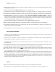
Gain Example for AVCS/Heading-hold Gyros (GY) GY 100% NOR 0% "Normal Mode" 100% AVC "Heading Hold Mode" -100% 0% +100% STD GOAL of EXAMPLE: Set up a heading-hold/AVCS gyro with heading-hold/AVCS setting in idle-ups 1 and 2 and normal mode setting in idle-up3 and normal. STEPS: INPUTS: Open and activate the GYRO function. for 1 second.(If basic, to GYRO. Optional: change Heading-hold (GY). gyro type to Optional: change switch assignment. Ex: select Cond. Adjust gyro rates as needed.
GOVERNORS: GV-1 connections Magnetic sensor Throttle servo Control amp Mixture servo Connected only when fuel mixture function used.
• Speed switching and governor ON/OFF may be together using one switch or ON/OFF switching may be performed using an independent switch/channel. • When speed setting control uses CH7 and separate ON/OFF switch is not used, CH8 can be used for other functions. • In-flight adjustment of the head speed (for easy adjustment during tuning) may be created using an additional channel and a programmable mix. See www.futaba-rc.com\faq\faq-9c.html for details.
GOAL of EXAMPLE: Set up a GV1 governor to use both channels into the receiver and switch between the governor settings automatically when changing conditions. Consider setting the battery FailSafe settings and other helpful functions on the GV-1 itself. STEPS: Open and activate the GOVERNOR function. INPUTS: for 1 second.(If basic, again.) to GOVERNOR. to ACT. Optional: change cut-off channel to channel 8 and assign switch and direction for on/off (channel 8). to CH8.
GLOSSARY 3D: Common name for certain types of aerobatic maneuvers. Aircraft: flying below the model’s stall speed, such as torque rolls. Helicopters: combining 2 or more maneuvers, such as rolling loop. 4.8V: 4.8 volt battery pack, made of 4 Ni-Cd 1.2V cells. See Accessories. 5-cell: 6.0 volt battery pack, made of 4 alkaline cells or 5 Ni-Cd cells. See Accessories. 6V (6Volt): battery pack, made of 4 alkaline cells or 5 Ni-Cd cells. See Accessories.
ATL: Adjustable Travel Limited. Standard type of trim used for throttle, where the trim is effective only in the idle portion of the THROTTLE STICK POSITION. Normal trims affect the entire travel of the servo (ex: elevator trims), but ATL trims only the low end of the throttle movement, allowing throttle idle adjustments that don’t over-drive the servo at full throttle. . . . . . . . . . . . . . . .31 ATV: Older, less clear terminology for end point adjustment. See END POINT.
Copy model: see MODEL COPY. Crow: see BUTTERFLY (GLID) and AIRBRAKE (ACRO). Cursor: See SELECT BUTTONS. Curve Mix: a mix that does not have the same reaction at all points along the master channel. See Programmable mix. Cyclic: horizontal controls on a helicopter. Cyclic pitch is typically called elevator. Cyclic roll is typically called aileron. Data reset: erase all data in a specific model. See RESET. DELAY: (HELI) slows the servo’s reaction time when changing from one condition to another.
Elevator-to-pitch mix: (HELI) used to adjust pitch to counter the loss of angle of attack when elevator input is given. Not a preprogrammed mix. See Programmable mix. This is the default setting of one mix in HELI. ELEVON: flying wing configuration with 2 servos working together to create both aileron and elevator action. See Twin elevator servos. . . . . . . . . . . . . . . . . . . . . . . . . . . . . . . . . . . . . . . . . . . . . . . . . . . . . . . . . . . . . . . . . . . . . . . . . . . . . . .
GOVERNOR: (HELI) programming which eases the setup of the GV-1 governor. . . . . . . . . . . . . . . . . . . . . . . . . . . . . . .89 GV-1: part number/name for Futaba’s electronic governor. See Gyros and Governors and GOVERNOR for details. Gyro, gyroscope: equipment that senses change in direction and provides input to compensate for that change. For description of aircraft use, see p. 64. For description of types, and helicopter use, see GYRO SENS.
Linear Mix: a mix that maintains the same relationship of master to slave throughout the whole range. Ex: a mix from one flap servo to another flap servo at 100% causes the 2nd servo to follow the first servo’s movement exactly through all points of travel. See Programmable mix. LINK: mixing function that allows multiple mixes to work in conjunction. See Programmable mix. Lithium battery: see Backup battery. Linear: linear, directly proportional. See AIRBRAKE.
Ni-Cd: Nickel Cadmium rechargeable battery. Typically used to power transmitter and receiver. See Battery care and charging. NiMH: Nickel Metal Hydride rechargeable battery. Newer battery technology than Ni-Cd. Longer run times but more specific peak charging requirements. [Require a (zero) delta peak charger labeled specifically for use with NiMH batteries.] NORMAL: trainer mode that does not give student radio the computer programming features of the master radio. See Trainer.
Rudder-to-throttle mix: (HELI) adds throttle to counter the added load from increasing pitch of the tail blades, maintaining a constant head-speed with rudder. (This is a minor effect and is not critical in most helicopters.) Not a preprogrammed mix. See Programmable mix. Rx: receiver. SAFE MODE: feature in snap roll programming that does not allow a snap roll if landing gear is lowered. See Snap roll. Sailplane: glider, non-powered model aircraft type. See GLID / MODEL TYPE.
Technical Specifications. . . . . . . . . . . . . . . . . . . . . . . . . . . . . . . . . . . . . . . . . . . . . . . . . . . . . . . . . . . . . . . . . . . . . . . . .9 Thermal hunting setup: using specific programming setups to have the model respond noticeably to the lift of a thermal. Not a preprogrammed mix. See Programmable mix. THR-DELAY: (ACRO) throttle delay, slows engine servo response to imitate the spool-up action of a turbine engine.
VR(A-C) are knobs; VR(D-E) are sliders on the case sides. V-tail model Mix: (ACRO / GLID) programming used to control a V-tail model’s tail surfaces, with 2 servos operating 2 control surfaces as both rudder and elevator. See Twin elevator servos. Warning messages: cautions provided by the radio when certain potential problems exist. See Error messages. Warranty information. . . . . . . . . . . . . . . . . . . . . . . . . . . . . . . . . . . . . . . . . . . . . . . . . . . . . . . . . . . . . . . . . . . .