MOBEXCOM DVE Users Manual 8A084X03 Rev. 1.
DVE 1. TABLE OF CONTENTS Section 1. Page TABLE OF CONTENTS .....................................................................................................2 Notes, Attentions, Important....................................................................................................3 MODES ..........................................................................................................................................................7 CONTROL HEAD ......................................
DVE Notes, Attentions, Important Throughout this manual, you will see Notes, and Attentions, Important Their meaning is as follows: NOTE A clarifying statement that expands on the text that follows. IMPORTANT An important statement that should be considered and / or implemented in order to achieve adequate equipment operation. ATTENTION! An instruction that must be followed in insure compliance with the appropriate standards or proper equipment operations. Futurecom Systems Group Inc.
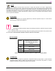
DVE NOTE This equipment has been tested and found to comply with the limits for a Class A digital device, pursuant to Part 15 of the FCC Rules. These limits are designed to provide reasonable protection against harmful interference when the equipment is operated in a commercial environment. This equipment generates, uses, and can radiate radio frequency energy and, if not installed and used in accordance with the instruction manual, may cause harmful interference to radio communications.
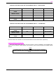
DVE RADIO OPERATOR Futurecom requires the MOBEXCOM DVE operator to ensure FCC Requirements for Radio Frequency Exposure are met. The DVE output power has to be set such that the maximum power into 0dBd (2.15dBi) omni directional antenna does not exceed 3.0W at the antenna connector. The minimum distance between all possible personnel and the antenna at 3.0W must be at least as shown in Table 1.
DVE Trunk lid For optimum performance and compliance with RF Energy Safety standards, mount the DVE antenna in the center area of the trunk. Before installing an antenna on the trunk lid: Ensure that the distance from the antenna location on the trunk lid will be at least the distance specified in Table 1 from the front surface of the rear seat-back to assure compliance with RF Energy Safety standards.
DVE 2. INTRODUCTION The Futurecom MOBEXCOM DVE® is designed to interface to a range of mobile radios and control heads. It permits expanded operation of portable radios. The DVE system consists of a mobile radio, MOBEXCOM DVE® unit and a mobile radio Control Head. The Control Head communicates with the DVE and the mobile using a serial data protocol. MODES The DVE operates in one of two modes. The mode of operation is selectable from the Mobile Control Head by the mobile radio operator.
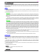
DVE ‘Zone’ ‘Page’ ‘Monitor’ ON/OFF ‘Alarm’ (Δ) ‘Private’ (∅) ‘ mode’ selection (H/L) ‘Phon’ ‘Scan’ ‘Call’ ‘Opt’ ‘Home Menu’ ‘Sel’ LED Indicators for: ‘Mobile Transmit’ (Red LED) ‘Mobile Receiver Busy’ (Orange LED) Display: Alphanumeric LCD (with backlighting) Indicators are provided to display the receiver and transmitter status of the mobile. The ‘Mobile Transmit’ red indicator lights whenever the mobile transmitter is keyed.
DVE 3. OPERATION CONTROL HEAD The DVE Control Head selects mode of operation for both the and the Mobile Radio. To Turn the ON or OFF Press the button in the Volume knob located on the left side of the control unit. The display should become active when the system turns ON. A test message appears briefly on the display. When the system is turned ON, the Mobile Channel and DVE Mode will automatically return to the same settings that were in effect when the power was last turned OFF.
DVE CONTROL HEAD INDICATORS AND ALPHANUMERIC DISPLAY – MOBILE MODE STATE ‘MOBILE BUSY’ ‘MOBILE XMIT’ MOBILE RECEIVE WITH CTCSS MOBILE RECEIVE WITHOUT CTCSS MICROPHONE PTT ON ‘ZONE CHANNEL’ ON ‘ZONE CHANNEL’ ON DISPLAY ‘ZONE CHANNEL’ ‘ZONE CHANNEL’ ‘ZONE CHANNEL’ RECEIVE WITH CTCSS RECEIVE WITHOUT CTCSS CONTROL HEAD INDICATORS AND ALPHANUMERIC DISPLAY – SYSTEM MODE STATE ‘MOBILE BUSY’ ‘MOBILE XMIT’ MOBILE RECEIVE WITH CTCSS MOBILE RECEIVE WITHOUT CTCSS RECEIVE WITH CTCSS RECEIVE WITHOUT CTCS
DVE Other Button and Knob Functions The available functions are: • ‘Monitor’ - unmutes speaker audio when Mobile or DVE RF carrier is present. • ‘H/C’ - changes Repeat mode of operation. • ‘Call’ - sends call signal via Mobile transmission. • ‘Opt’ - dims alphanumeric display. All other buttons and knobs function as programmed in the standard mobile radio. Please refer to the mobile radio’s documentation for details of operation. Futurecom Systems Group Inc. DVE Users Manual 8A084X03_Rev1_3.
DVE APPENDIX 1 General Specifications Dimensions Height / Width / Depth Weight Channel Spacing 92mm (3.63”) / 186mm (7.32”) / 315mm ( 12.41”) 5.2 kg (11.5 lbs) approx. 12.5 kHz or 25 kHz Analog Voice or P25 Modulation Power Supply DC Current Drain 13.8 VDC ± 20%, negative ground only OFF Max. 0.01 A RPTR Standby Max. 0.8 A Receive Max 0.8 A Transmit Max. 2.