MOBEXCOM DVRS Vehicular Repeater Users Manual 8A083X03 Rev. 2.
DVRS Vehicular Repeater System 1. TABLE OF CONTENTS Section 1. Page TABLE OF CONTENTS .....................................................................................................2 Notes, Attentions, Important....................................................................................................3 REPEATER MODES....................................................................................................................................6 CONTROL HEAD .........................
DVRS Vehicular Repeater System Notes, Attentions, Important Throughout this manual, you will see Notes, and Attentions, Important Their meaning is as follows: NOTE A clarifying statement that expands on the text that follows. IMPORTANT An important statement that should be considered and / or implemented in order to achieve adequate equipment operation. ATTENTION! An instruction that must be followed in insure compliance with the appropriate standards or proper equipment operations.
DVRS Vehicular Repeater System NOTE This equipment has been tested and found to comply with the limits for a Class A digital device, pursuant to Part 15 of the FCC Rules. These limits are designed to provide reasonable protection against harmful interference when the equipment is operated in a commercial environment.
DVRS Vehicular Repeater System ANTENNA INSTALLATION IMPORTANT Refer to Futurecom 8F083X03 or 8F083X05 Product Safety and RF Energy Exposure Booklet for antenna installation instructions. FCC Label This device complies with Part 15 of the FCC Rules. Operation is subject to the following two conditions: 1) This device may not cause harmful interference, and 2) This device must accept any interference received, including interference that may cause undesired operation.
DVRS Vehicular Repeater System 2. INTRODUCTION The Futurecom MOBEXCOM DVRS® Vehicular Repeater is designed to interface to a range of mobile radios and control heads. It permits expanded operation of portable radios. The Vehicular Repeater system consists of a mobile radio, MOBEXCOM DVRS® Vehicular Repeater unit, a mobile radio Control Head and a RF multiplexer. The Control Head communicates with the Vehicular Repeater and the mobile using a serial data protocol.
DVRS Vehicular Repeater System The mobile user simultaneously keys both the Mobile radio and Vehicular Repeater transmitters when using the microphone Push-to-Talk. The Vehicular Repeater receiver has full priority over the mobile radio operator microphone Push-to-Talk. The mobile radio operator microphone Push-to-Talk has priority over the Mobile receiver.
DVRS Vehicular Repeater System Indicators are provided to display the receiver and transmitter status of the mobile. The ‘Mobile Transmit’ red indicator lights whenever the mobile transmitter is keyed. The ‘Mobile Receiver Busy’ orange indicator lights whenever the receiver is busy, regardless of presence or absence of any CTCSS (Channel-Guard) tone coding.
DVRS Vehicular Repeater System 3. OPERATION CONTROL HEAD The Repeater Control Head selects mode of operation for both the Repeater and the Mobile Radio. To Turn the Repeater ON or OFF Press the button in the Volume knob located on the left side of the control unit. The display should become active when the system turns ON. A test message appears briefly on the display.
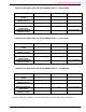
DVRS Vehicular Repeater System CONTROL HEAD INDICATORS AND ALPHANUMERIC DISPLAY – MOBILE MODE REPEATER STATE ‘MOBILE BUSY’ ‘MOBILE XMIT’ DISPLAY MOBILE RECEIVE WITH CTCSS MOBILE RECEIVE WITHOUT CTCSS MICROPHONE PTT ON ‘ZONE CHANNEL’ ON ‘ZONE CHANNEL’ ON ‘ZONE CHANNEL’ ‘ZONE CHANNEL’ REPEATER RECEIVE WITH CTCSS REPEATER RECEIVE WITHOUT CTCSS ‘ZONE CHANNEL’ CONTROL HEAD INDICATORS AND ALPHANUMERIC DISPLAY – LOCAL MODE REPEATER STATE ‘MOBILE BUSY’ ‘MOBILE XMIT’ DISPLAY MOBILE RECEIVE WITH CT
DVRS Vehicular Repeater System Functions Disabled in LOCAL and SYSTEM Repeat Modes There are several control unit button and knob functions, which are disabled in the LOCAL and SYSTEM repeat modes. These are Scan activation, Mode selection, Zone selection, Home channel operation and Mobile channel selection. NOTE A standard audible error signal “bop” as well as an error message is displayed ‘RLOC VR ACTIVE’ or ‘RSYS VR ACTIVE’ if any of the above functions are attempted in the LOCAL or SYSTEM repeat modes.
DVRS Vehicular Repeater System APPENDIX 1 General Specifications Dimensions Height / Width / Depth Weight Channel Spacing 92mm (3.63”) / 186mm (7.32”) / 315mm ( 12.41”) 5.2 kg (11.5 lbs) approx. 12.5 kHz or 25 kHz Analog Voice or P25 Modulation DC Current Drain Power Supply 13.8 VDC ± 20%, negative ground only Repeater OFF Max. 0.01 A RPTR Standby Max. 0.8 A Receive Max 1.7 A @ 7.5 W Audio @ 13.8 VDC Transmit Max. 6.