
User's Manual

Vehicular Repeater System
Futurecom Systems Group ULC. 8A083X22 Rev 4_3E.docxDOC Rev. Preliminary Page 9
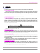
‘Opt’
‘Home Menu’
‘Sel’
LED Indicators for
:
‘Mobile Transmit’ (Red LED)
‘Mobile Receiver Busy’ (Orange LED)
Display
:
Alphanumeric LCD (with backlighting)
Indicators are provided to display the receiver and transmitter status of the mobile. The ‘Mobile Transmit’ red
indicator lights whenever the mobile transmitter is keyed. The ‘Mobile Receiver Busy’ orange indicator lights
whenever the receiver is busy, regardless of presence or absence of any CTCSS (Channel-Guard) tone coding.
REPEATER RADIO UNIT
The Repeater is designed to implement a Vehicular Repeater System, to provide portable radio users greater
communication range by repeating signals through the vehicle's mobile radio to the dispatch centre. Various modes of
repeater operation are available, to suit different operational requirements. The Vehicular Repeater Radio is the
central connection point for the vehicular system. It connects to an external Control Head and Mobile Radio.
It includes all the necessary hardware for repeater operations. The Repeater is housed in a weather resistant
metal enclosure with 2 removable covers. The covers provide protection for the connectors. The Repeater is mounted
on a RF multiplexer.
The Repeater communicates with the control head and the mobile radio via serial communication bus.
MOBILE RADIO UNIT
The Mobile Radio used in the Vehicular Repeater System is a standard mobile radio. Refer to the mobile radio’s
user manual for details of operation of this radio. The Vehicular Repeater is designed to operate with a variety of
mobile radio units.