
Installation Instructions
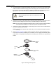
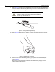
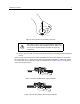
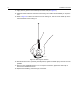
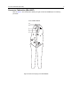
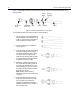

Table Of Contents
- Foreword
- Product Safety and RF Exposure Compliance
- Before using this product, read the operating instructions for safe usage contained in the Product Safety and RF Exposure booklet enclosed with your radio.
- ATTENTION!
- This radio is restricted to occupational use only to satisfy FCC RF energy exposure requirements. Before using this product, read the RF energy awareness information and operating instructions in the Product Safety and RF Exposure booklet enclosed wi...
- For a list of Motorola-approved antennas, batteries, and other accessories, visit the following website: http://www.motorola.com/governmentandenterprise
- Document Copyrights
- Disclaimer
- Trademarks
- VHF Vehicle Roof-Top Antennas HAD4021A HAD4022A
- Installation Manual
- Introduction
- Tuning Instructions for the HAD4022A Gain Antenna
- FCC Requirements
- Motorola Recommendations for Vehicle Roof-Top Antenna Locations
- Required Tools and Materials
- Installation Procedure
- Connector Fabrication (Mini-UHF)
- Tuning Chart for HAD4022A
- Product Safety and RF Exposure Compliance

10 Connector Fabrication (Mini-UHF)
Figure 10 illustrates the order in which the mini-UHF connector items must be assembled on the
antenna cable.
Figure 10. Mini-UHF Connector Components
To assemble the mini-UHF cable connector, do the following:
1. Trim the jacket, the braided shielding,
and the dielectric of the cable to 6 mm
(0.24 in.) from the end of the cable in
order to expose the center wires.
2. Trim the jacket back an additional
10 mm (0.4 in.)
3. Insert the cable into the crimp making
sure that the flange of the crimp is
facing towards the end of the cable,
and then insert the cable into the
shell. Be sure that the shell end with
the larger diameter opening is facing
towards the end of the cable.
4. Solder the gold-plated center pin to
the center wires by adding solder to
the hole in the back of the pin. Then,
while heating the center pin so that
the solder remains melted, insert the
wires fully into the pin.
Note: Ensure that no solder is
allowed to adhere to the outside of the
center pin.
5. Insert the cable into the connector
body while ensuring that the center
pin is pushed as far forward as
possible and allowing the braided
shielding to extend on the outside of
the connector body.
Connector
Body
Gold-Plated
Center Pin
Shell
Crimp
Dielectric
Center
Wires
Braided
Shielding
Jacket