
Installation Instructions

8F083X03 Rev 15
DVRS-Product Safety and RF Exposure Booklet 26
NOTE: VHF and UHF 1/4 wave antenna should be mounted on the roof, not on the trunk lid, to
ensure compliance with RF Energy Exposure regulations.
5. Ensure that the antenna cable can be easily routed to the radio. Route the antenna cable
as far away as possible from any vehicle electronic control units and associated wiring.
6. Check the antenna location for any electrical interference.
NOTE: Any two metal pieces rubbing against each other (such as seat springs, shift levers, trunk
and hood lids, exhaust pipes, etc.) in close proximity to the antenna can cause severe receiver
interference.
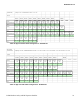
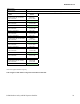
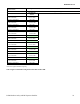
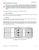
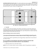
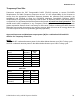
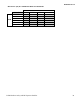
Fig 3 Multiple Antennas Separation for locations 1-10
Fig. 3 indicates the separation distances required for the various antennas used with an APX 8500
midpower radio. Each "cross-hair" symbol represents a possible location (i.e. LOC) of an antenna.
The recommendation is to locate them as close to the center of the roof and/or trunk as possible,
without interference with a lightbar. This picture is not drawn to scale. For letters A, B, C, and D, the
table indicates the EXACT distance for separation of the LMR antennas. For letters E, F, G, and H,
the table indicates the maximum distance between the edge of the ground plane and the accessory
antenna location.
NOTE:
• A minimum of 18 inch separation is required between lightbar and any roof mounted antennas, to
prevent interference with the lightbar circuitry (see lightbar manufacturer’s installation information).
• The LMR 700/800 antennas should only be placed at LOC:2 or LOC:5.
• Standard LMR VHF and UHF antennas should only be placed at LOC:1, LOC:3, LOC:4 and LOC:6.
• 1/4 wave LMR VHF and UHF antennas should only be placed at LOC:1 and LOC:3 (i.e. Roof only)
to ensure compliance with RF Energy Exposure regulations.
• The VML antenna must be separated from any LMR antenna by at least 40 inches.