
Installation Instructions
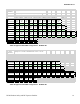
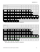
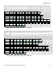
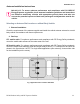
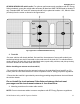
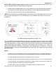
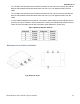
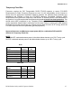
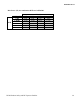
Table Of Contents
- Document Revisions
- Notes, Attentions, Important
- RF Exposure Label
- FCC Label
- Installation Requirements for Compliance with Radio Frequency (RF) Energy Exposure Safety Standards
- Table 5A Approved 800 DVRS Configurations – APX6500 / APX7500
- Table 5B Approved 700 DVRS Configurations – APX6500 / APX7500
- Table 5C Approved UHF R1 DVRS Configurations – APX6500 / APX7500
- Table 5D Approved UHF R2 DVRS Configurations – APX6500 / APX7500
- Table 5E Approved UHF R3 DVRS Configurations – APX6500 / APX7500
- Table 5F Approved VHF DVRS Configurations – APX6500 / APX7500
- Table 6A Approved 800 DVRS Configurations – APX8500
- Table 6B Approved 700 DVRS Configurations – APX8500
- Table 6C Approved UHF R1 DVRS Configurations – APX8500
- Table 6D Approved UHF R2 DVRS Configurations – APX8500
- Table 6E Approved UHF R3 DVRS Configurations – APX8500
- Table 6F Approved VHF DVRS Configurations – APX8500
- Antenna Installation Instructions
- Mobile Radio / DVR Antenna separation
- Fixed DVRS Site Antennas

8F083X03 Rev 13
DVRS-Product Safety and RF Exposure Booklet 25
• The LTE Main and Diversity Antenna locations should be at LOC:9 and LOC:10 when the LMR All-
Band or LMR 700/800 narrow band antennas are at LOC:2 (i.e LTE opposite location from the
LMR).
• The LTE Main and Diversity Antenna locations should be at LOC:7 and LOC:8 when the LMR All-
Band or LMR 700/800 narrow band antennas are at LOC:5 (i.e LTE opposite location from the
LMR).
• In some mobile installations that include an LTE modem, external filtering on the LMR port and/ or
the LTE port may be needed to reduce interference. Contact your local Motorola Solutions Service
Center for more information and for filter kit numbers (See Appendix for contact info).
Table 7 Distance between Antenna
Multiplexers and Vehicle Installation
Fig.4 Multiplexer Views