
Installation Instructions

8F083X03 Rev 16.1
DVRS-Product Safety and RF Exposure Booklet 28
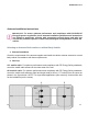
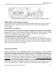
• The LMR 700/800 antennas should only be placed at LOC:2 or LOC:5.
• Standard LMR VHF and UHF antennas should only be placed at LOC:1, LOC:3, LOC:4 and LOC:6.
• 1/4 wave LMR VHF and UHF antennas should only be placed at LOC:1 and LOC:3 (i.e. Roof only)
to ensure compliance with RF Energy Exposure regulations.
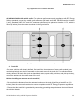
• The VML antenna must be separated from any LMR antenna by at least 40 inches.
• The LTE Main and Diversity Antenna locations should be at LOC:9 and LOC:10 when the LMR All-
Band or LMR 700/800 narrow band antennas are at LOC:2 (i.e LTE opposite location from the
LMR).
• The LTE Main and Diversity Antenna locations should be at LOC:7 and LOC:8 when the LMR All-
Band or LMR 700/800 narrow band antennas are at LOC:5 (i.e LTE opposite location from the
LMR).
• In some mobile installations that include an LTE modem, external filtering on the LMR port and/ or
the LTE port may be needed to reduce interference. Contact your local Motorola Solutions Service
Center for more information and for filter kit numbers (See Appendix for contact info).
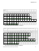
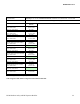
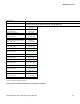
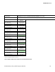
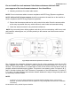
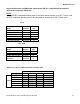
Table 7 Distance between Antenna
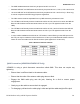
QMA Connection (APX8500/APX8500 HP Only)
APX8500 is using a quick disconnect connection called QMA. This does not require any
tightening.
• Ensure there is sufficient slack in the antenna cable.
• Ensure that the collar of the antenna cable plug does not bind.
• Engage the QMA cable plug onto the jack, listening for a click to ensure proper
engagement.
• Gently tug on the cable to ensure that it is engaged.
• To disengage, pull back on the cable plug’s collar and pull the cable straight off the jack.