
User's Manual


Vehicular Repeater System
Futurecom Systems Group ULC. 8A083X22 Rev 4_2E.docxDOC Rev. Preliminary Page 12
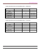
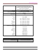
CONTROL HEAD INDICATORS AND ALPHANUMERIC DISPLAY – SYSTEM MODE
REPEATER STATE
‘MOBILE BUSY’ ‘MOBILE XMIT’ DISPLAY
MOBILE RECEIVE WITH
CTCSS
ON ‘RS TX CHANNEL’
MOBILE RECEIVE
WITHOUT CTCSS
ON ‘RSYS CHANNEL’
MICROPHONE PTT
ON ‘RS TX CHANNEL’
REPEATER RECEIVE
WITH CTCSS
ON ‘RS RT CHANNEL’
REPEATER RECEIVE
WITHOUT CTCSS
‘RS RX CHANNEL’
Note that ‘ZONE’ and ‘CHANNEL’ are the selected Mobile zone and channel names, respectively.
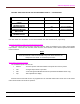
Functions Disabled in LOCAL and SYSTEM Repeat Modes
There are several control unit button and knob functions, which are disabled in the LOCAL and SYSTEM
repeat modes. These are Scan activation, Mode selection, Zone selection, Home channel operation and Mobile
channel selection.
NOTE
A standard audible error signal “bop” as well as an error message is displayed
‘RLOC VR ACTIVE’ or ‘RSYS VR ACTIVE’ if any of the above functions are
attempted in the LOCAL or SYSTEM repeat modes.
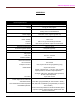
Other Button and Knob Functions
The available Repeater functions are:
‘Monitor’ - unmutes speaker audio when Mobile or Repeater RF carrier is present.
‘H/C’ - changes Repeat mode of operation.
‘Call’ - sends call signal via Mobile transmission (SYSTEM and MOBILE mode only).
‘Opt’ - dims alphanumeric display.
All other buttons and knobs function as programmed in the standard mobile radio. Please refer to the mobile
radio’s documentation for details of operation.