
Installation Instructions
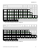
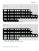
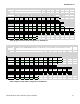
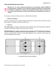
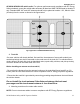
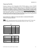
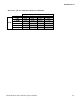
Table Of Contents
- Document Revisions
- Notes, Attentions, Important
- RF Exposure Label
- FCC Label
- Installation Requirements for Compliance with Radio Frequency (RF) Energy Exposure Safety Standards
- Table 5A Approved 800 DVRS Configurations – APX6500 / APX7500
- Table 5B Approved 700 DVRS Configurations – APX6500 / APX7500
- Table 5C Approved UHF R1 DVRS Configurations – APX6500 / APX7500
- Table 5D Approved UHF R2 DVRS Configurations – APX6500 / APX7500
- Table 5E Approved UHF R3 DVRS Configurations – APX6500 / APX7500
- Table 5F Approved VHF DVRS Configurations – APX6500 / APX7500
- Table 6A Approved 800 DVRS Configurations – APX8500
- Table 6B Approved 700 DVRS Configurations – APX8500
- Table 6C Approved UHF R1 DVRS Configurations – APX8500
- Table 6D Approved UHF R2 DVRS Configurations – APX8500
- Table 6E Approved UHF R3 DVRS Configurations – APX8500
- Table 6F Approved VHF DVRS Configurations – APX8500
- Antenna Installation Instructions
- Mobile Radio / DVR Antenna separation
- Fixed DVRS Site Antennas

8F083X03 Rev 13
DVRS-Product Safety and RF Exposure Booklet 22
Antenna Installation Instructions
IMPORTANT: To assure optimum performance and compliance with FCC/ISED RF
Energy Exposure regulations, these antenna installation guidelines and instructions
are limited to metal-body vehicles with appropriate ground planes and take into
account the potential exposure of back seat passengers and bystanders outside the
vehicle.
Selecting an Antenna Site/Location on a Metal Body Vehicle
1. External installation
Check the requirements of the antenna supplier and install the vehicle antenna external to a metal
body vehicle in accordance with those requirements.
2. Roof top
XTL mobile radio: For optimum performance and compliance with RF Energy Safety standards,
mount the mobile radio antenna in the center area of the roof.
APX mobile radio: For optimum performance and compliance with RF Energy Safety standards,
mount the mobile radio antennas (dual and single band) at 45cm (17.7 inches) from the center as
shown in the figure below. NOTE: For single band applications (one antenna), choose either side
for the installation (not the center).
Fig.1 Applicable to XTL and Non APX 8500