
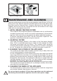
Murano Collection Complete Manual
25
Phase 3
- To prevent the hood from detaching if pressure is exerted from beneath,
secure it to the wall with the brackets supplied (fig. O3).
- Fit pipe/hose (E) into (D).
Phase 4
- Slide the extension (H) into (G) till the desired height.
- When the extension is at the desired height, screw it onto the chimney with
the screws supplied (V1);
- Lock the chimney + extension onto the hood with 6 V2 screws.
- Fit the glass panels (fig. O5).
O2 - INSTRUCTIONS FOR MIRABILIA ISLAND 67
Phase 1
- Identify the desired height (H1=65 cm) of the hood.
- Slide the internal support frames (C) and (C1) till the desired height (H2),
then lock them with 8 self-tapping screws (V2) (Fig.O6).
Phase 2
- Fit the extension to the chimney (Fig. O6).
- If the hood is of extraction type: identify the desired height of the exhaust
pipe/hose and connect it to the motor connection.
Phase 3
- Lift the hood and hook it onto the 4 M5 metric screws (V4) pre-screwed to the
internal support frame (centre the Ø11 holes with the slot of the reinforce-
ment frame and move the frame sideways) (Fig. O7a).
- Tighten the 4 M5 screws (V4) (Fig. O7b).
- Connect the pipe/hose to the exhaust hole on the ceiling (it the hood is of
extraction type).
- Connect the electrical system after having disconnected the power supply.
- Fit the extension to the internal support frame with 4 M4 metric screws (V3),
(Fig. O8).
- Use extension brackets (A) (Fig. O9) only if the top internal support frame is
not used, or if there is a false ceiling.
- Fit the glass panels (fig. O5).
O3 - INSTRUCTIONS FOR MIRABILIA ISLAND 85/ISLAND 67
CENTRAL CHIMNEY
Phase 1
- Identify the desired height (H1=65) for the positioning of the hood.
- Slide the lattice-works (C) and (C1) to the desired height (H2), then block
them with the 8 self-threading screws (V2) (Fig.1a).
- Fasten the lattice-work (C) to the ceiling using the four Ø 8 expansion plugs
and relative screws(V1) (Fig.1b).
Phase 2
- Insert the extension on the flue and fasten them to each other with masking
tape (Fig. 2).
- Fasten the flue-extension assembly (D+E) to the lattice-work (C) with the 4
M4 metric screws (V3) inserted in the existing holes without tightening them