
Use and Care Manual


24
SAFETY WARNINGS
M
The electrical system features an earth connection in compliance with interna-
tional safety standards; furthermore, it is compliant with the European standard
for electromagnetic compatibility.
Do not connect the appliance to flues (from boilers, fireplaces, etc.). Make sure
the mains voltage corresponds to the values on the rating plate located inside
the range hood. The minimum safety distance between the cooktop and the
range hood must be at least 65 cm.
Never cook on “open” flames under the range hood.
Check deep-fryers during use: superheated oil may be flammable.
- Ensure there is adequate ventilation of the room when the rangehood is used
at the same time as appliances burning gas or other fuels.
- Do not flambe under the rangehood
- The exhaust air must not be discharged into a flue which is used for exhaust-
ing fumes from appliances burning gas or other fuels.
- Ensure that all regulations concerning the discharge of exhaust air have been
fulfilled before you use the appliance.
Before performing any cleaning or maintenance operations, disconnect the ap-
pliance by unplugging it or using the main switch. The manufacturer disclaims
all liability for any damage that may be directly or indirectly caused to people,
things and animals due to the failure to follow all the instructions provided in
this booklet and above all the warnings relating to the installation, operation
and maintenance of the appliance.
WARRANTY
N
The new equipment is covered by warranty.
The warranty conditions are provided by the distributor.
The manufacturer is not liable for any inaccuracies in this booklet resulting
from printing or transcription errors. The manufacturer reserves the right to
modify its products as it considers necessary or in the interests of the user,
without compromising their essential safety and operating characteristics.
HOOD INSTALLATION
O
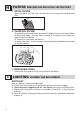
O1 - INSTRUCTIONS FOR WALL-MOUNTED MIRABILIA HOODS
Phase 1
- Place the support bar next to the wall (A-Fig. O1), at a height above the cook-
top which corresponds to X+300 mm.
- With a spirit level check that the bar is horizontal. Mark a point at each end
of the bar.
- Drill the holes, fit 2 ø8mm expansion joints and screw in the bar.
Phase 2
- Fit the hood to the support bar (Fig. O2).
- Adjust hood alignment with the relevant screws: The top screw (B) adjusts
the distance from the wall. The bottom screw (C) adjusts the vertical sliding
movement.