
Instruction Book


10
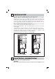
pletely (Fig. 2).
- For suction version: identify the optimal height for the rigid or flexible
exhaust pipe (F) and connect it to the motor connection.
Step 3
- Raise the hood, hooking it onto the 4 M5 metric screws (V4) pre-tightened to the
lattice-work (C) (center the Ø11 holes on the slot of the inner liner and move it
laterally)(Fig. 3a).
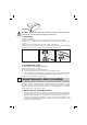
- Completely tighten the 4 M5 screws (V4) (Fig. 3b).
- Remove the masking tape (Fig. 3c), remove the four M4 metric screws (V3)
previously tightened onto the lattice-work (Fig. 3d) and slide the flue-extension
assembly downwards. (Fig. 3e).
- Connect the pipe to the connection of the ceiling discharge hole. (Fig. 3f).
- Make electrical connections only after having removed electrical power supply.
- Fasten the extension to the lattice-work (C) by means of the 4 M4 metric
screws(V3), without tightening them completely(Fig. 3g).
- Cut to size the slot-covers (H) and insert them (Fig. 3h).
- Block the extension completely to the lattice-work (C) by screwing down the 4
M4 metric screws (V3).
- Block the flue with the 2 self-threading screws (V5) (Fig. 3i).
- Use the extension support elements(A) (Fig. 2) only if the upper lattice-work is
not used, or in the case of a false ceiling.
V4
V5
V3
V3
F
3a
3a
3i
3a
3b
3d
3h
3d
3c
3e
3f
3g
V3
H
H
Fig. 3