G-scan2 User Manual 3.3. Data + Simulation G-scan2 conducts the Measurement function’s simulation function that sends out the electric signal to the sensor / actuator wire while showing the Data Analysis function’s data list simultaneously.
G-scan2 User Manual 3.4. Data + Multimeter G-scan2 shows the actual multi-meter readings using its measurement function and displays the data values received from the control unit using the Data Analysis function enabling the direct comparison between the actual reading and the data processed by the control unit. 4. Data Record (trigger mode) 4.1.
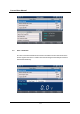
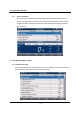
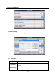
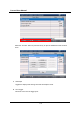
G-scan2 User Manual 4.2. Data Recording Select “Function” or press the [F6] key from the Data List display, then select [Record] button among the functions list. 4.3. Trigger Mode Select Trigger Mode either Manual Record or DTC Record. Button Manual Record DTC Record Description Trigger point is recorded when the “Trigger” button is manually selected by the user. Trigger point is recorded automatically when the G-scan2 reads the DTC from the control unit.
G-scan2 User Manual In the same dialog window, the range of the recorded parameters can be selected either “Selected Items” or “All items”. Please note that selecting All Items will consume more memories, therefore will reduce the number of recordable frames with the given memory size. When OK is selected, the Data Recording will start. Check the red dot “Record” sign in the top right corner.
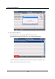
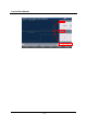
G-scan2 User Manual and retry. 4.4. Recorded Data Review Recorded Data can be reviewed by Flight Record Review function. Select the file and press “Run” button or “F1” key to load the recorded data. The recorded data can be played forward and reverse using the record player control buttons in the bottom or the relevant F1~F4 keys.
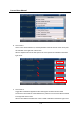
G-scan2 User Manual Select the “Function” button or press the F6 key to open the additional control functions menu A. Text/Graph Toggles the display mode among Text mode and Graphic mode. B. Go to Trigger Moves the cursor A to the trigger point.
G-scan2 User Manual C. Recorded Data Info Shows the details of the Recorded Data file currently being displayed. D. Item List G-scan2 Flight Record Review function for Hyundai and Kia may show up to 4 parameters at a time. If you have recorded more than 4 parameters and want to select the other parameters to be displayed in the graphical forms, you may select the desired parameters from the “Sensor Name” list as shown below.
G-scan2 User Manual E. Two Cursor A Cursor A is a vertical red dot line, and the parameter values at the time of the cursor point are indicated on the right side of the screen. Also the elapsed time from the start point to the cursor position is indicated in the bottom right corner. F. Two Cursor B Trigger B is activated and appears as the vertical green dot line as shown below. The minimum and maximum values between the positions of Cursor A and B are indicated in the right side of the screen.
G-scan2 User Manual 119
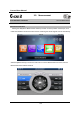
G-scan2 User Manual 3.5. Measurement AA-3-5. Measurement G-scan2 Basic Functions Measurement Function Utilizing the VMI(Vehicle Measurement Interface) module. G-scan2 provides oscilloscope, multimeter and simulation functions that are used for measuring the electric signals from the wire directly. Select the [Measurement] icon from the main menu to run the Measurement Functions, then the Measurement Menu follows as below.
G-scan2 User Manual Oscilloscope Function Measures the voltage or amperage fluctuations of the vehicle’s sensor or actuator circuits in rapid repetition and visualizes the signals in the graphic waveforms. Measurement of cylinder compression is also possible by the use of optional pressure sensor. The signal input ports of G-scan2 VMI module are assigned to specific measurement functions, so please refer to the following table.
G-scan2 User Manual 1. Oscilloscope Upper Section Control Menu When [2CH] is selected from the Measurement Functions menu, the Oscilloscope function runs in 2 Channel mode as shown below. : The sensors and actuators of Engine and Transmission that are frequently used are listed and the optimal voltage and time division setting are provided for each item as the preset values. Simply select the sensor or actuator name from the list and no manual voltage and time division level adjustment is necessary.
G-scan2 User Manual The [Help Tip] icon is activated when the item is selected from the [Preset] menu, where the general description about the selected sensor/actuator as well as the waveform analysis guide and the reference waveform are provided.
G-scan2 User Manual : Opens the User Setting menu where the Channel, Threshold and Display settings can be configured manually. A. Channel Configuration Saves the user’s current oscilloscope time and voltage settings. The saved settings can be retrieved from the menu, which enables the oscilloscope setting procedure quick and simple when measuring the same sensor again later.
G-scan2 User Manual In the examples below, the same waveforms are displayed in both Channel A and B, however, please note that no frequency and duty readings are indicated in the Channel B, because the threshold level is set out of the range of the Channel B signal. Threshold level needs to be positioned within the signal range in order to measure the frequency and duty cycle.
G-scan2 User Manual C. Display Setup Signal line thickness and the channel name / measurement readout indication settings can be configured. Line Thickness Thickness of waveform lines can be selected among 1 point and 2 points. Channel Name / Measurement Readout Channel name indication in the top of each channel window and the measurement readouts in the right side of the screen can be toggled ON or OFF.
G-scan2 User Manual : Changes the settings for each channel. You can enable or disable the individual channel, and also change the signal range and the settings for each channel.
G-scan2 User Manual [ Configuration for AUX ] Configuration Description Modes UNI Centered by 0 level, the waveform is displayed in (+) field only. BI Centered by 0 level, the waveform is displayed in both (+) and (-) fields. AC Used for measuring the AC voltages (ex. Alternator Diode ripple voltage) DC Used for measuring the DC voltage Peak Normal Auto Manual Senses and displays the surge voltages when measuring the parts that include the coil, i.e.
G-scan2 User Manual Data 1, 2, 3: Selects among the 3 groups of measurement readouts are indicated in the top of each channel window.
G-scan2 User Manual : Toggles the digital readings On/Off in the right side of the screen. ■ Easier way to activate the “Digital Reading” Touch the yellow circle area on the screen and drag it to the left. window will be dragged out from the end of the screen.
G-scan2 User Manual Reversely, you can hide the digital readings by touching the center area where marked with yellow circles, then drag it to the right. : Saved oscilloscope waveforms can be selected and reviewed..
G-scan2 User Manual : Shows the signals of all channels overlapped on the single window which is useful for checking the missing signal or synchronization of the signals.
G-scan2 User Manual : Indicates the time difference between cursor A and cursor B Press ‘A’ or ‘B’ button, then the selected cursor is indicated by turning to red, and the selected cursor can be moved by touching the desired position on the screen. : Time division can be adjusted by using the left-right buttons.
G-scan2 User Manual 2. Oscilloscope Lower Section Control Menu : Cancels the current settings and refreshes the screen. : Switches to 2 Channel or 4 channel mode. In 2 Channel mode, Channel B can be switched to the scope mode or the pressure sensor mode.
G-scan2 User Manual [ Channel Setting – 2CH + AUX mode ] For both 2 CH and 4 CH modes, Channel Aux can be configured for Amperage measurement by selecting the small or large current sensor.
G-scan2 User Manual : Performs zero setting for resistance, small and large current and pressure measurement. : Sets the trigger in 3 modes: Rise, Fall and no trigger. [Note] “Trigger” is originated from the crossbow or gun’s trigger, which holds the passing waveforms still for a short time when the trigger condition is met.
G-scan2 User Manual Multi-meter Function G-scan2 provides digital meter function through the VMI that performs the measurement of voltage, resistance, frequency, duty cycle and pulse width as well as the continuity test. 1. Multi-meter Upper Section Control Menu : Measures the voltage in the circuit through channel B of the VMI.
G-scan2 User Manual : Conducts the Continuity Test on the circuit. If the circuit is normal and not open, high tone buzzer sounds and the resistance is indicated.
G-scan2 User Manual : Measures the frequency of the input signal through the VMI channel B. : Measures the duty of the input signal through VMI channel B. Toggle the polarity of the pulse by selecting [+] or [-].
G-scan2 User Manual : Measures the pulse width of the input signal through the channel B of the VMI. Pulse [+] and [-] values changed when selecting either [+] or [-].
G-scan2 User Manual 2. Multi-meter Lower Section Control Menu : Multi-meter function settings can be configured. Guide for resistance meter calibration, continuity test buzzer and the related data display when measuring Frequency / Duty / Pulse can be enabled or disabled.. Also the line thickness of the graphing meter function that is presented in the lower half of the multi-meter screen can be selected among 1, 2, 3 or 4 point(s).
G-scan2 User Manual Display Set Description Main digital meter readout only Main digital meter readout and the reference data Graphing meter Main digital readout pattern only and the graphing meter pattern : Conducts the meter calibration for resistance measurement. Calibration is recommended before measuring the resistance, please follow the onscreen guide to do the calibration. The calibration guide can be disabled from the configuration button in the bottom.
G-scan2 User Manual Simulation Function G-scan2 can actively send out the electric signals to the vehicle’s sensor or actuator circuit for indepth diagnostic purposes. 1. Voltage Output Sends out the continued voltage signal to the circuit through the VMI channel B, and the voltage level can be manually adjusted by the user. Mainly used for checking the sensor signal wire. Please observe the instruction displayed in the lower half of the G-scan2 screen.
G-scan2 User Manual 2. Pulse Output Sends out the 5V pulse signal of the frequency as controlled by the user up to 1kHz through VMI channel B. Mainly used for checking the digital signal sensors like wheel speed sensor.
G-scan2 User Manual 3. Duty Output Conducts the test on the actuators such as injectors by sending out the signals of frequency and duty as controlled by the user, through the VMI channel A. A. Hz Select Hz button to adjust the frequency of the output duty signal.
G-scan2 User Manual B. Duty (%) Select Duty (%) button to adjust the duty cycle of the output signal.
G-scan2 User Manual 3.6. Favorite AA-3-6. Favorite G-scan2 Basic Functions Favorite The special functions of the specific vehicle models that are frequently used can be added to the favorite list where the listed functions can be simply executed having to make the whole lot of vehicle details selecting procedures. 1. Adding the function to the list Add a special function to the favorite list by selecting “Favorite” or pressing the [F1] key from the special functions menu.
G-scan2 User Manual Select the special function with the Star+ mark , then the function is added to the favorite list with your confirmation. When done, exit the Favorite List control menu by selecting “Back” or pressing the [F1] key.
G-scan2 User Manual 2. Loading the favorite list Select “Favorite” icon from the main menu, then the folders are listed as shown below. Folder Recents “Manufacture name” Description The advanced functions that have been recently used are listed automatically. The advanced functions that the user has manually added as the Favorite functions are listed in the car manufacturer name folders.
G-scan2 User Manual Select one among the list and select “OPEN” or press the [F1] key to start the function. The selected function will be executed directly from this list without having to make any further selections. Select “MAKER” or press the [F3] key to return to the folder selection menu. Select “DELETE” or press the [F6] key to remove the selected special function from the list.