
User Manual
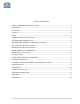
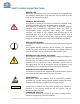
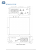
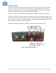
Table Of Contents
- SAFETY OPERATION INSTRUCTIONS
- OVERVIEW
- FCC NOTE
- IC NOTE
- NOTE
- ANTENA INSTALLATION NOTE
- RF EXPOSURE WARNING-FCC
- RF EXPOSURE WARNING- INDUSTRY CANADA
- ELECTRICAL SPECIFICATIONS
- MECHANICAL SPECIFICATIONS
- ENVIRONMENTAL CONDITIONS
- MECHANICAL OUTLINE
- CONNECTIONS
- AVAILABLE, OPTIONAL FEATURES
- ALARM CONDITIONS
- VARIABLE GAIN ADJUSTMENT AND LED INDICATORS
- INSTALLATION
- OPERATION
- DIAGNOSTICS GUIDE
- APPENDIX 1
- APPENDIX 2

9 | Page
CONNECTIONS
The RF connections are made via two “N-type” female connectors. The RF connector labeled
"DL IN" /" UL OUT" must be connected to the antenna pointing towards the base station or
connected to Head-End unit. The RF connection labeled “MOBILE” must be connected to the
antenna / passive DAS facing the area to be covered by the BDA.
The RF connections must be made through cables with characteristic impedance of 50 ohms.
The BDA AC power is accepted through a standard 3-wire male plug (IEC-320) with phase,
neutral and ground leads. The AC power is wired to a high efficiency DC switching power supply
which is CE and UL approved. The power supply runs the amplifiers and the LED indicators. The
metal enclosure of the BDA is connected to ground.
Additional monitoring connectors are available as described in the “Features” section.
Figure 4: Back Panel Connections