
User Manual


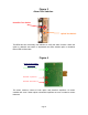

Downlink Test Switch
The BDA has two momentary test switches to verify the alarm function. When the
uplink or downlink test switch is depressed the alarm boards uplink or downlink
failure LED will illuminate.
Figure 4
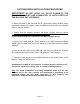
The alarm monitors current of both uplink and downlink amplifiers. An alarm
condition will occur if either uplink or downlink amplifiers are over or under its current
tolerance.
Page 8
Uplink Test Switch
Alarm Board Amplifier
Status LEDs
Green LED-System OK
Red LED – Uplink Fail
Red LED –Downlink Fail
Figure 3
Alarm Test Switches