
User Manual


BDA OPERATION
Variable Step Attenuator
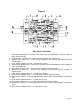
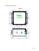
BDA gain can be reduced by up to 30 dB in 2 dB steps using the variable step
attenuator (Figure 4). Gain adjustment is made with rotary switches accessible via the
access door on the BDA enclosure. Arrows on the shafts of these switches point to
the value of attenuation selected. BDA gain can be determined by subtracting the
attenuation value from the gain reported on the BDA Test Data Sheet for that side of
the unit. The attenuators are labeled for Uplink and Downlink.
Alarm Function
The alarm monitors current of both uplink and downlink amplifiers in each path (PCS
and Cellular). An alarm condition will occur in each path if either the uplink or downlink
amplifiers are over or under its current tolerance or there is no supply power present.
(Relay Shown in Non-Alarm Condition)
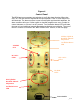
ALC (Automatic Level Control)
To minimize intermodulation products, the Uplink and Downlink amplifiers in the BDA
contain an ALC feedback loop. The ALC circuit senses the output power and limits it
to the factory-preset level of +26 dBm. A red indicator lamp located on each the
control panel illuminates when output power meets or exceeds the ALC set point
(Figure 4).
Note: Depending on the BDA’s input signal, the red indicator lamp may not illuminate.
In this case, position the “BASE” antenna in the direction of the closest Base station.
To establish proper operating gain on the Uplink and Downlink sides, start with the
Downlink. Verify that the attenuator is set the maximum position of 30 dB. Observe the
red indicator lamp on the Downlink amplifier. Decrease attenuation one step at a time
until the lamp is lit. Then, using the Downlink step attenuator, increase the attenuation
until the lamp goes off. Repeat the process for the Uplink. The level indicator is
accurate to +/- 0.4 dB of the ALC set point. Note: The recommended operation of
the BDA is when the factory set ALC is turned on. Operation of the BDA in the
alarm condition will void the warranty, and output power should be immediately
reduced using the variable step attenuator.
Operation of BDA-CELLAB/PCSF-2/2W-80-OCA1with greater than 0 dBm
average power incident on the MOBILE or BASE ports can cause damage to the
BDA.
Page | 11