
User Manual


Optional Features:
OCAG: Automatic Gain Reduction
When this option is selected, the part number will be changed to BDA-CELLAB/PCSF-
2/2W-80-OCAG. This option protects the BDA from oscillation due to service
upgrades. Should the input RF signal increase due to a service upgrade, the unit will
detect potential oscillation and automatically drop the system’s gain by 30 dB,
preventing interference until a service technician adjusts the system (antenna
separation, location etc.)
Lightning protector
When this option is selected, the part number will be changed to BDA-CELLAB/PCSF-
2/2W-80-OCA2. This option protects the BDA from lightning through the RF BASE
and MOBILE ports.
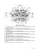
OUTDOOR BDA INSTALLATION PROCEDURE
Page | 12
IMPORTANT: DO NOT APPLY A.C. POWER TO THE BDA UNTIL CABLES ARE
CONNECTED TO BOTH PORTS OF THE BDA AND THE ANTENNAS.
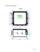
1. Mount the BDA on the wall with the RF connectors pointing DOWN. Using appropriate
screws and anchors, attach the BDA to the wall at the six mounting holes on the side
flanges.
2. Ensure that the isolation between the donor antenna and the service antenna is at
least 12 dB greater than the BDA gain. (Use the higher of the Uplink and Downlink
gains reported on the BDA test data sheet).
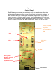
3. Connect the cable from the donor antenna to the BDA connector labeled “BASE” and
the cable from the service antennas to the BDA connector labeled “MOBILE”.
4. Connect the AC power cord to the BDA and then to the power source. Turn the BDA’s
power switch to the “ON” position. Verify that the “Power On” indicator is lit.
*NOTE: Due to the inconsistency of generators in the field, G-Wave recommends
the use of a Power Line Conditioner on the AC source.
Installation of the BDA is now complete.